Engines Iveco C10,C13, Cursor 10, Cursor 13. Manual - part 84
Check for any water in the fuel filter
The components of the system can be damaged
very quickly in presence of water or impurity within
the fuel.
Take prompt action on the filter to drain off the
water in the fuel circuit.
Fuel filter is equipped with pump screw-valve to drain the
water eventually mixed with fuel.
Place a container underneath the filter and slightly loosen the
screw. Drain the water eventually contained in the filter’s
bottom.
Lock the screw (max 0.5 Nm locking couple) as soon as fuel
starts bleeding.
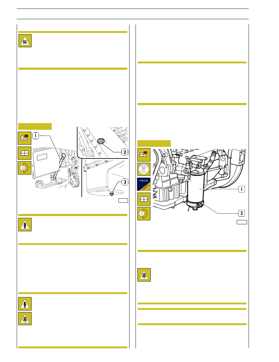
Figure 34
85493
We recommend to carry out the oil drainage when the motor
is hot.
Engine oil change
- Place a proper container for the oil collecting under the
pan connected with the drain plug (3).
- Unscrew the plug (3) and then take out the control dip-
sick (1) and the inserting plug (2) to ease the downflow
of the lubrication oil.
Warning: We recommend to wear proper protec-
tions because of high motor service temperature.
The motor oil reaches very high temperature: you
must always wear protection gloves.
The oil motor is very pollutant and harmful.
In case of contact with the skin, wash with much water
and detergent.
Protect properly skin and eyes: operate according to
safety rules.
Dispose of the residual properly following the rules.
Lock plus (3) under oil sump at predefined tightening torque.
Pour oil in prescribed quantity and quality in engine through
filler (2) of tappet cover.
- After the complete drainage, screw the plug and carry out
the clean oil filling.
Use only the recommended oil or oil having the re-
quested features for the corrrect motor function-
ing.
In case of topping up, don’t mix oils having different
features.
If you don’t comply with theses rules, the service
warranty is no more valid.
- Check the level through the dipsick until when the filling
is next to the maximum level notch indicated on the dip-
sick.
NOTE
Engine oil filter change
Figure 35
107940
Warning: the oil filter contains inside a quantity of
oil of about 1 kg.
Place properly a container for the liquid.
Warning: avoid the contact of skin with the motor
oil: in case of contact wash the skin with running
water.
The motor oil is very pollutant: it must be disposed
of according to the rules.
Drain oil as described in “Engine oil change” chapter.
By means of 99360314 tool (2) to disassemble oil filter (1) or
filters for F3B engine .
Before refitting the new cartridge, wet seal using
engine oil.
NOTE
Lock oil filter (1) by hand till contact to support and then lock
by
¾ of a rev. at prescribed tightening torque; pour oil in
engine ad described in “Engine oil change” chapter.
NOTE
34
SECTION 2 - G-DRIVE APPLICATION
CURSOR ENGINES G-DRIVE
Base - May 2007