Engine Iveco C10/C13/C78/Cursor 13/Cursor 78. Manual - part 11
SECTION 3 - INDUSTRIAL APPLICATION
19
Apply the tool 99360321 (6) to the gearbox (3).
45261
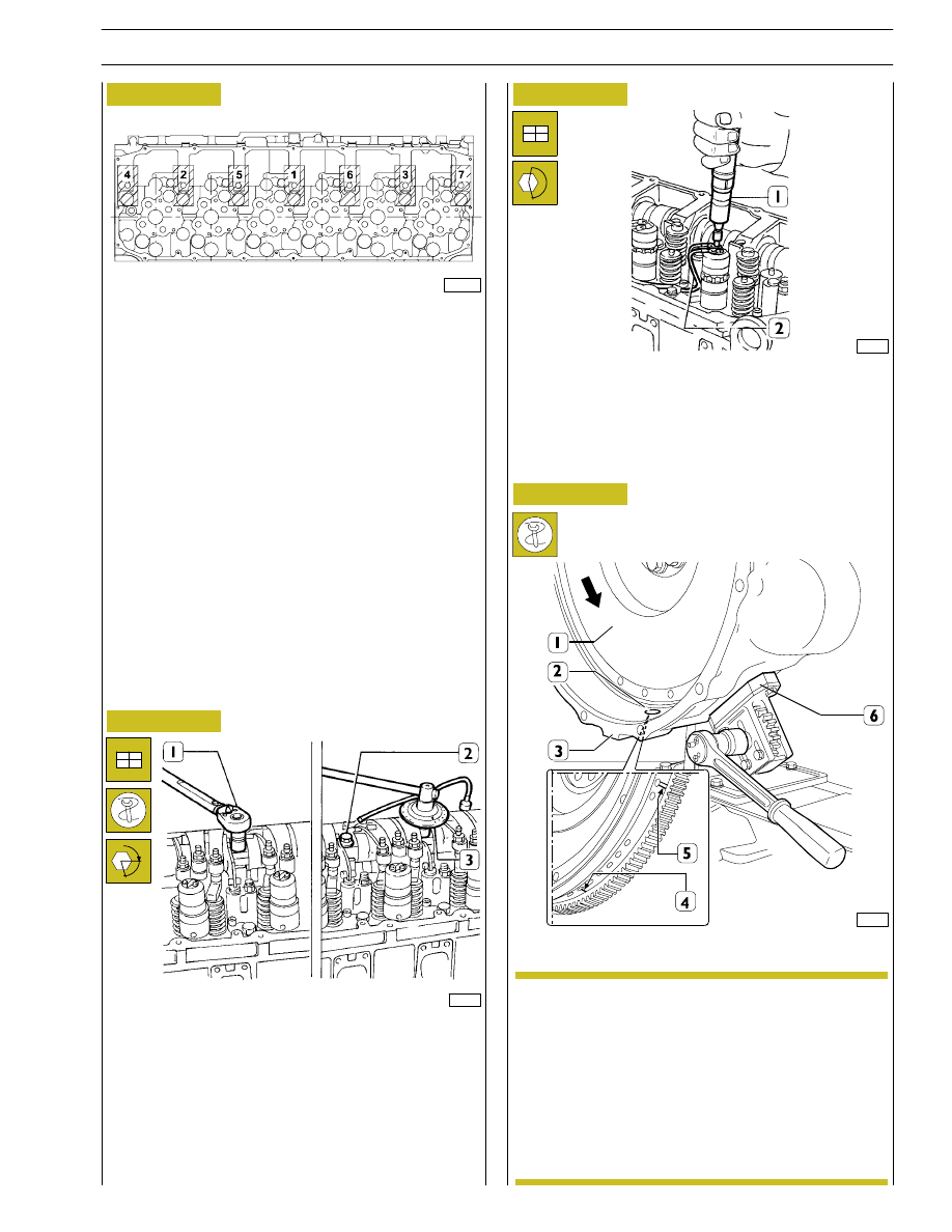
Lock the screws (2) fixing the rocker-arm shaft as follows:
- 1
st
phase: tightening to a torque of 80 Nm (8 kgm) with
the torque wrench (1);
- 2
nd
phase: closing with an angle of 60
° using the tool
99395216 (3).
Mount the electric wiring (2), securing it on the
electro-injectors with a torque screwdriver (1) to a torque
of 1.36 - 1.92 Nm.
α
The arrow shows the direction of rotation of the
engine when running.
Using the above-mentioned tool, turn the engine
flywheel (1) in the direction of rotation of the
engine so as to take the piston of cylinder no.1 to
approximately the T.D.C. in the phase of
combustion.
This condition occurs when the hole with one
reference mark (4), after the hole with two
reference marks (5) on the engine flywheel (1), can
be seen through the inspection window (2).
Figure 55
Figure 56
Figure 57
Camshaft timing
71776
71777
SCHEME OF SCREW TIGHTENING SEQUENCE
SECURING ROCKER ARMS
Screw screws (1 - 2 - 3) until rocker arms are brought to
contact relating seats on cylinder head, tighten the screws
according to sequence indicated in figure operating in two
steps as indicated in successive figure.
70567A
NOTE
Figure 58