Isuzu Amigo / Axiom / Trooper / Rodeo / VehiCross. Manual - part 887
 

  Index      Isuzu     Isuzu Amigo / Axiom / Trooper / Rodeo / VehiCross - service repair manual 1999-2002 year


Search            


Content   ..  885  886  887  888   ..


Isuzu Amigo / Axiom / Trooper / Rodeo / VehiCross. Manual - part 887


6E–572

TROOPER 6VE1 3.5L ENGINE DRIVEABILITY AND EMISSIONS

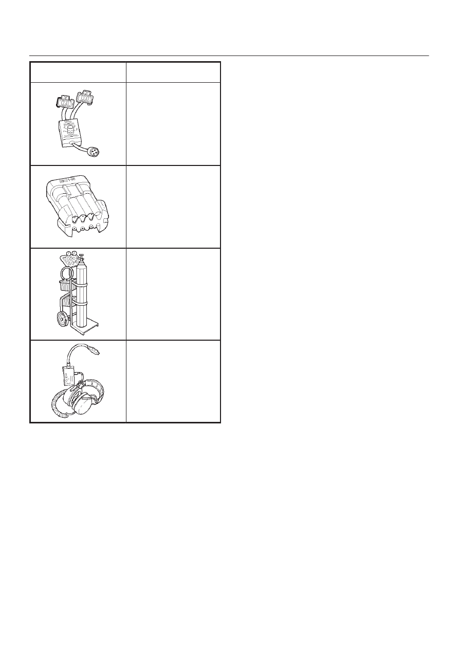
ILLUSTRATION

TOOL NO.

TOOL NAME

J 39021-90

Injector Switch Box

J 39021-65

Injector Test Light

J 41413

!

EVAP Pressure/Purge

Diagnostic Station

J 41416

@

Ultrasonic Leak Detector

1. J 41413 EVAP Pressure/Purge Diagnostic Station is

a multipurpose tool which is used to perform several
diagnostic procedures for enhanced emission
testing.  The station will accommodate a nitrogen gas
filled cylinder which is used to pressurize the vehicle
EVAP system for a leakdown test and leak location
test when a vehicle is repaired for leakage in the
enhanced evaporative emission control system.  It
also has two additional gauges (inches of mercury
and inches of water) which are used to measure both
source vacuum and EVAP canister purge vacuum to
verify correct operation and vapor flow within the
canister purge circuit.

2. J 41416 Ultrasonic Leak Detector is a

microprocessor-based device used to detect leaks in
the enhanced evaporative emission control system.
The evaporative system is pressurized to 30 inches of
water using the J 41413 EVAP Pressure/Purge
Diagnostic System.  Small leaks in the EVAP system
will emit sound at a high frequency undetectable by a
human ear but detectable with the J 41416.  The
technician traces along the evaporative system and
can pinpoint leaks due to corroded lines, cracked
hoses, or a damaged EVAP component.  The
detector includes a high quality set of headphones to
block out surrounding shop noise and the LED
sensitivity meter allows a visual reference for locating
leaks in conjunction with the audio output heard
through the headphones.  Powered by (1) nine volt
battery.

6F–1

ENGINE EXHAUST

TROOPER

ENGINE

ENGINE EXHAUST

CONTENTS

General Description

6F–2

. . . . . . . . . . . . . . . . . . . . . 

Front Exhaust Pipe

6F–3

. . . . . . . . . . . . . . . . . . . . . . 

Front Exhaust Pipe and Associated Parts

6F–3

Removal

6F–3

. . . . . . . . . . . . . . . . . . . . . . . . . . . . . 

Installation

6F–3

. . . . . . . . . . . . . . . . . . . . . . . . . . . . 

Three Way Catalytic Converter LH

6F–4

. . . . . . . . . 

Removal

6F–4

. . . . . . . . . . . . . . . . . . . . . . . . . . . . . 

Installation

6F–4

. . . . . . . . . . . . . . . . . . . . . . . . . . . . 

Three Way Catalytic Converter RH

6F–5

. . . . . . . . 

Removal

6F–5

. . . . . . . . . . . . . . . . . . . . . . . . . . . . . 

Installation

6F–5

. . . . . . . . . . . . . . . . . . . . . . . . . . . . 

Exhaust Silencer

6F–6

. . . . . . . . . . . . . . . . . . . . . . . . 

Exhaust Silencer and Associated Parts

6F–6

. . . 

Removal

6F–6

. . . . . . . . . . . . . . . . . . . . . . . . . . . . . 

Installation

6F–6

. . . . . . . . . . . . . . . . . . . . . . . . . . . . 

Rear Exhaust pipe

6F–7

. . . . . . . . . . . . . . . . . . . . . . . 

Rear Exhaust pipe and Associated Parts

6F–7

Removal

6F–7

. . . . . . . . . . . . . . . . . . . . . . . . . . . . . 

Installation

6F–7

. . . . . . . . . . . . . . . . . . . . . . . . . . . . 

Main Data and Specifications

6F–8

. . . . . . . . . . . . . 

SECTION

6F–2

ENGINE EXHAUST

General Description

150R200017

When inspecting or replacing exhaust system
components, make sure there is adequate clearance
from all points on the underbody to prevent overheating
the floor pan and possible damage to the passenger
compartment insulation and trim materials.

Check complete exhaust system and nearby body areas
and rear compartment lid for broken, damaged, missing
or mispositioned parts, open seams, holes, loose
connections or other deterioration which could permit
exhaust fumes to seep into the rear compartment or
passenger compartment. Dust or water in the rear
compartment may be an indication of a problem in one of
these areas. Any faulty areas should be corrected
immediately.

Hangers

Various types of hangers are used to support exhaust
system(s). These include conventional rubber straps,
rubber rings, and rubber blocks.

The installation of exhaust system supports is very
important, as improperly installed supports can cause
annoying vibrations which can be difficult to diagnose.

Three Way Catalytic Converter

The three way catalytic converter is an emission control
device added to the exhaust system to reduce pollutants
from the exhaust gas stream.

CAUTION: The catalytic converter requires the use
of unleaded fuel only.
Periodic maintenance of the exhaust system is not
required. If the vehicle is raised for other service, it is
advisable to check the condition of the complete exhaust
system.
A dual bed monolith catalytic converter is used in
combination with three way catalytic converter.
Catalytic Types:
Three way (Reduction/Oxidation) catalyst
The catalyst coating on the three way (reduction)
converter contains platinum and rhodium which lowers
the levels of nitrous oxide (NOx) as well as hydrocarbons
(HC) and carbon monoxide (Co).

Gasket

The gasket must be replaced whenever a new exhaust
pipe, muffler or catalytic converter is installed.

6F–3

ENGINE EXHAUST

Front Exhaust Pipe

Front Exhaust Pipe and Associated Parts

150R200005

Legend

(1) Gasket
(2) Front Exhaust Pipe RH Fixing Nuts
(3) O

2

 Sensor Harness Connector

(4) Front Exhaust Pipe RH Fixing Bolts and Nuts
(5) Gasket
(6) Front Exhaust Pipe Fixing Bolts and Nuts
(7) Gasket

(8) O

2

 Sensor Harness Connector

(9) Front Exhaust Pipe LH

(10) O

2

 Sensor Harness Connector

(11) Front Exhaust Pipe LH Fixing Nuts

(12) O

2

 Sensor Harness Connector

(13) Gasket
(14) Front Exhaust Pipe RH

Removal

1. Disconnect battery ground cable.
2. Raise the vehicle and support with suitable safety

stands.

3. Disconnect O

2

 sensor harness connector

(3)(8)(10)(12).

4. Remove front exhaust pipe fixing bolts and nuts

(4)(6).

5. Remove front exhaust pipe fixing three stud nuts (2)

(11) from exhaust manifold.

6. Remove front exhaust pipe (9)(14).

Installation

1. Install front exhaust pipe (9)(14) and tighten three

stud nuts (2)(11) and two nuts (4)(6) to the specified
torque.

Torque
Stud Nuts : 67 N·m (49 lb ft)
Nuts(4) : 57 N·m (42 lb ft)
Nuts(6) : 43 N·m (32 lb ft)

2. Reconnect O

2

 sensor harness connector

(3)(8)(10)(12).


Content   ..  885  886  887  888   ..