Isuzu Amigo / Axiom / Trooper / Rodeo / VehiCross. Manual - part 632
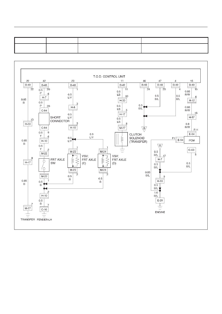
DRIVE LINE CONTROL SYSTEM (TOD)
4B2–48
Check flow
Trouble code
Phenomenon
Standard
10
26
The electromagnetic coil GND is
short-circuited.
Resistance: 1.0 to 5.0 ohm (at ordi-
nary temperature)
D04RY00008