Isuzu Amigo / Axiom / Trooper / Rodeo / VehiCross. Manual - part 567


  Index      Isuzu     Isuzu Amigo / Axiom / Trooper / Rodeo / VehiCross - service repair manual 1999-2002 year


Search            


Content   ..  565  566  567  568   ..


Isuzu Amigo / Axiom / Trooper / Rodeo / VehiCross. Manual - part 567


1A–136 HEATING, VENTILATION AND AIR CONDITIONING (HVAC)
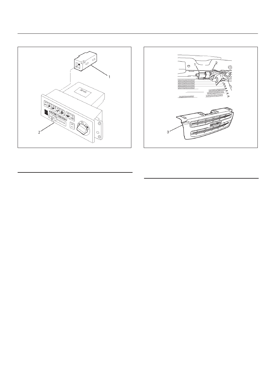
In Car Sensor

865RY00020

Legend

(1) In Car Sensor
(2) Automatic Air Conditioner Control Unit

Removal

1. Disconnect the battery ground cable.
2. Remove the automatic air conditioner control unit.

D

Refer to the automatic air conditioner control unit
section.

3. Remove in car sensor.

Installation

To install, follow the removal step in the reverse order.

Ambient Sensor

875R200030

Legend

(1) Ambient Sensor
(2) Sensor Connector
(3) Radiator Grille

Removal

1. Disconnect the battery ground cable.
2. Remove radiator grille.

D

Refer to Radiator Grille in Body Structure section.

3. Disconnect the ambient sensor connector.
4. Remove the ambient sensor.

Installation

To install, follow the removal step in the reverse order.

HEATING, VENTILATION AND AIR CONDITIONING (HVAC) 1A–137

Sun Sensor

826RY00012

Legend

(1) Sun Sensor

Removal

1. Disconnect the battery ground cable.
2. Remove the sun sensor.
3. Disconnect the sun sensor connector.

Installation

To install, follow the removal step in the reverse order.

Duct Sensor

874R200019

Legend

(1) Sensor Part
(2) Evaporator Core
(3) Evaporator Assembly
(4) Duct Sensor Assembly

Removal

1. Disconnect the battery ground cable.
2. Remove the evaporator assembly.

D

Refer to the evaporator assembly in this section.

3. Remove the duct sensor assembly.

Installation

To install, follow the removal step in the reverse order.

1A–138 HEATING, VENTILATION AND AIR CONDITIONING (HVAC)

Mode Actuator

860R200009

Legend

(1) Driver Knee Bolster Assembly
(2) Instrument Panel Driver Lower Cover

Assembly

(3) Mode Actuator
(4) Actuator Rod

Removal

1. Disconnect the battery ground cable.
2. Remove the instrument panel driver lower cover

assembly.

3. Remove the driver knee bolster assembly.

D

Refer to the Instrument Panel Assembly in Body
Structure section.

4. Remove the actuator rod.
5. Remove the mode actuator.

Installation

To install, follow the remove step in the reverse order.

Mix Actuator

860RY00009

Legend

(1) Instrument Panel Assembly
(2) Actuator Rod
(3) Mix Actuator
(4) Instrument Panel Center Bracket

Removal

1. Disconnect the battery ground cable.
2. Remove the instrument panel assembly.

D

Refer to the Instrument Panel Assembly in Body
and Accessories section.

3. Remove the instrument panel center bracket.
4. Remove the actuator rod.
5. Remove the mix actuator.

Installation

To install, follow the remove step in the reverse order.

HEATING, VENTILATION AND AIR CONDITIONING (HVAC) 1A–139

Intake Actuator

873RY00004

Legend

(1) Evaporator Assembly
(2) Intake Actuator
(3) Intake Actuator Connector

Removal

1. Disconnect the battery ground cable.
2. Discharge and recover refrigerant.

D

Refer to Refrigerant Recovery in this section.

3. Remove the evaporator assembly.

D

Refer to Evaporator Assembly section.

4. Disconnect the intake actuator connector.
5. Remove the intake actuator.

Installation

To install, follow the remove step in the reverse order.


Content   ..  565  566  567  568   ..