Isuzu Amigo / Axiom / Trooper / Rodeo / VehiCross. Manual - part 383
6E–562
6VE1 3.5L ENGINE DRIVEABILITY AND EMISSIONS
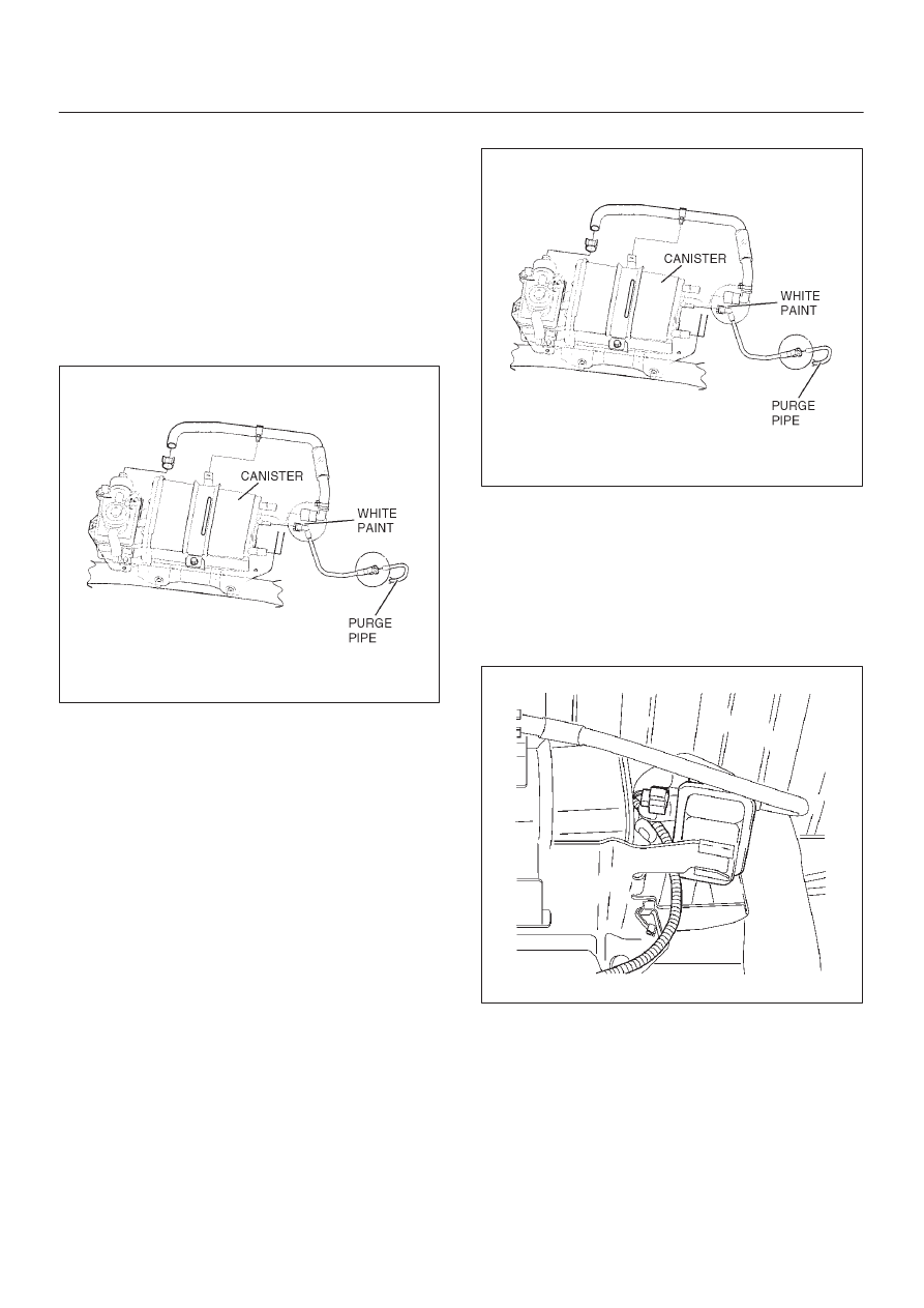
EVAP Canister
Removal Procedure
1. Disconnect the negative battery cable.
2. Disconnect the two hoses from the EVAP canister.
3. Disconnect the fuel vapor connector and the purge
hose from the EVAP canister vent solenoid.
4. Remove the two retaining bolts the EVAP canister to
the mounting bracket on the cross member.
5. Remove the retaining bolt on the mounting bracket
the slide the canister out of mounting bracket.
060R200081
Inspection Procedure
1. Inspect the hoses for cracks and leaks.
2. Inspect the canister for a damaged case.
Installation Procedure
1. Slide the canister into mounting bracket and install
the mounting bracket bolt.
2. Install the retaining bolts the EVAP canister to the
mounting bracket on the cross member.
3. Connect the fuel vapor connector to the EVAP
canister vent solenoid.
4. Connect the two hoses to the EVAP canister.
060R200081
5. Disconnect the negative battery cable.
EVAP Canister Vent Solenoid
Removal Procedure
1. Disconnect the negative battery cable.
2. Disconnect the connector and hose.
014RW132