Content .. 1150 1151 1152 1153 ..
Isuzu Amigo / Axiom / Trooper / Rodeo / VehiCross. Manual - part 1152
4C–20
DRIVE SHAFT SYSTEM
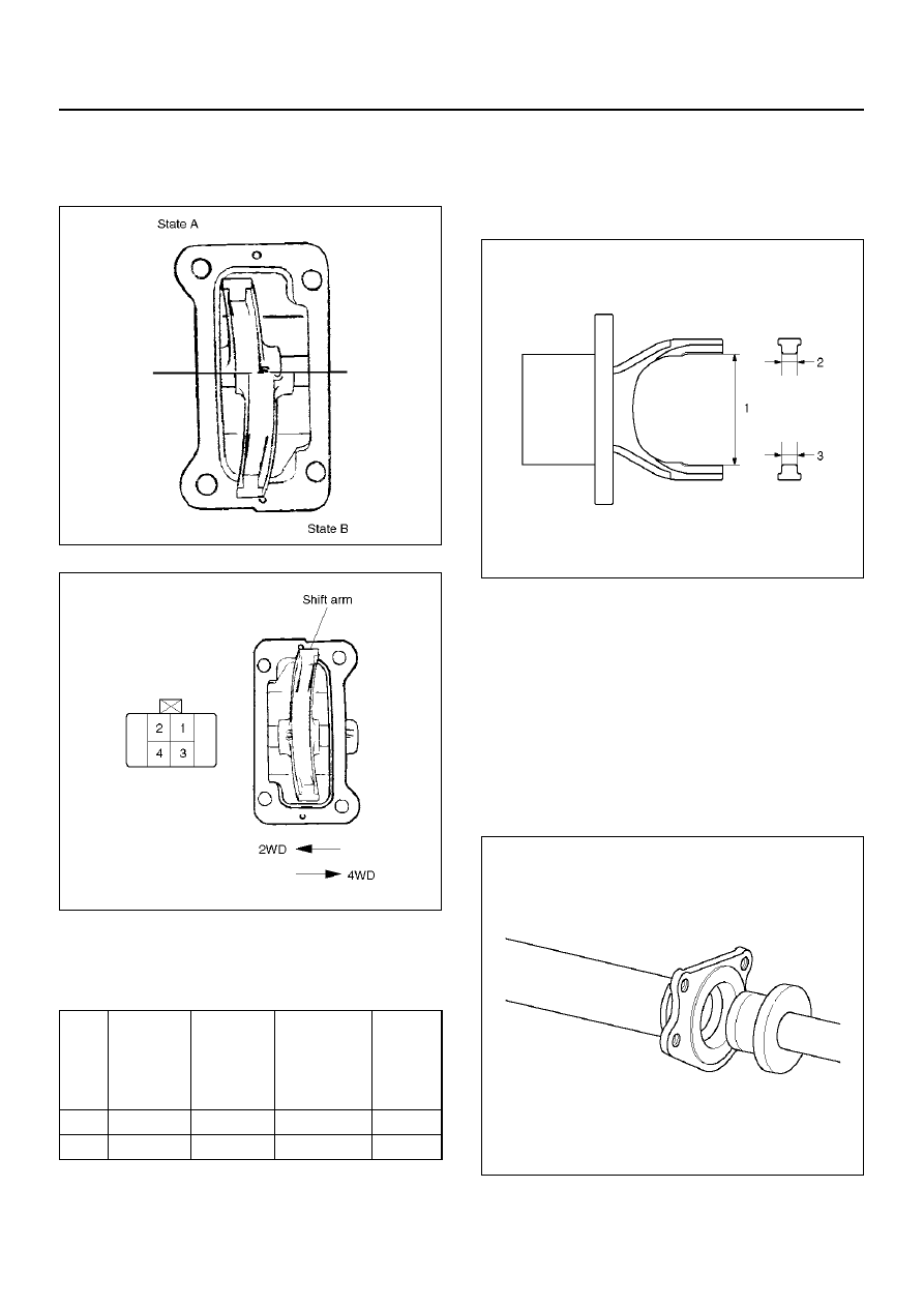
Actuator
Check and see that there is no damage, cracking, or
other abnormality.
Functional Check
412RY00041
412RY00009
Wake sure of function with boltage (12V) applied to
terminal 3, 4 and set the tester to terminal 1, 2 in
accordance with the table below.
If there is an abnormality, replace the actuator as an
assembly.
NOTE: Be careful not to permit the entry of water or
dust into of the actuator.
Dimentional Check
Measure illustrated sizes 1, 2, and 3.
412RY00010
Limit
1=64.3mm (2.53in)
2=6.7mm (0.26in)
3=6.7mm (0.26in)
Reassembly
1. Install the new oil seal which has been immersed in
differential gear oil, by using an oil seal installer J–
41693 and grip J–8092.
412RW034
State
Trminal 3
Trminal 4
Electric
circuit
between
terminal 1 &
2
Functio
n
A
+12V
Ground
OK
2WD
B
Ground
+12V
NONE
4WD