Isuzu Amigo / Axiom / Trooper / Rodeo / VehiCross. Manual - part 1137


  Index      Isuzu     Isuzu Amigo / Axiom / Trooper / Rodeo / VehiCross - service repair manual 1999-2002 year


Search            


Content   ..  1135  1136  1137  1138   ..


Isuzu Amigo / Axiom / Trooper / Rodeo / VehiCross. Manual - part 1137


4A2–16

DIFFERENTIAL (REAR)

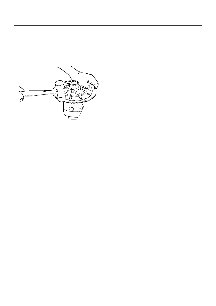
16. Remove exciter ring.

• Remove the exciter ring from the differential

using a mallet or a brass hammer if it is required.

NOTE:  Discard the exciter ring after removal.

425RS097

Cleaning

Do not steam clean drive parts which have ground and
polished surfaces such as gears, bearings, and shafts.
These parts should be cleaned in a suitable solvent. All
parts should be disassembled before cleaning.
Parts should be thoroughly dried immediately after
cleaning. Use soft, clean, lintless rags.   Parts may be
dried with cimpressed air. Do not allow the bearings to
spin while drying them with compressed air.

Inspection and Repair

It is very important to carefully and thoroughly inspect all
drive unit parts before reassembly.
Thorough inspection of the drive parts for wear or stress
and subsequent replacement of worn parts will
eliminate costly drive component repair after
reassembly.

Axle Housing

• The carrier bore for nicks or burrs that would prevent

the outer diameter of the pinion seal from sealing,
Remove any burrs that are found.

• The bearing cap bores for nicks or burrs.

Remove any burrs that are found.

• The housing for cracks. Replace the housing if any

cracks are found.

• The housing for foreign material such as metal chips,

dirt, or rust.

Pinion and Ring Gear

• Pinion and ring gear teeth for cracking, chipping,

scoring, or excessive wear.

• Pinion splines for wear.

• Pinion flange splines for wear.

• The sealing surface of the pinion flange for nicks,

burrs, or rough tool marks which would cause
damage to the seal's inside diameter and result in an
oil leak.

• Replace all worn or broken parts.

• Ring and pinion gears are matched sets and are both

replaced anytime a replacement of either is
necessary.

Bearings

• Bearings visually and by feel.

• The bearings should feel smooth when oiled and

rotated while applying as much hand pressure as
possible.
The large end of the bearing rollers for wear.
This is where tapered roller bearing wear is most
evident.

• Bearing cups for wear, cracks, brinelling and scoring.

• Bearing and cups are only replaced as sets.

• If the rear axle was operated for an extended period

of time with very loose bearings, the ring gear and
drive pinion will also require replacement.

• Low mileage bearings may have minute scratches

and pits on the rollers and the bearing cups from the
initial pre-load. Do not replace a bearing for this
reason.

• Bearing cups for cracks or chips.

Shims

• Shims for cracks and chips. Damaged shims should

be replaced with an equally sized service shim.

DIFFERENTIAL (REAR)

4A2–17

Reassembly

1. Install pinion bearing races and baffle plate using

outer bearing race installer J–8611–01 / inner
bearing race installer J–42836 and drive handle J–
8592.

NOTE:  Baffle plate must be installed, when install the
inner pinion bearing race.

425RW019

425RW020

2. Clean all the gauge parts.

3. Lubricate the outer and inner bearings with axle

lubricant.

4. Place the bearings into the pinion bearing races.

5. Place the inner oil slinger onto the inner pinion

bearing.

NOTE:  The inner oil slinger must be placed between
gauge plate and inner pinion bearing when measuring
the pinion depth.

6. Install gauge plate J–39837–2, inner J–42827 stud

and nut J–21777–43 and outer pilot J–42824 to the
pinion bore.

420RW005

7. Hold the stud stationary at the flats of the stud (and).

Tighten the stud nut

Torque: 2.2 N·m (1.6lb ft)

8. Rotate the gauge plate and bearings several

complete revolutions to seat the bearings.

9. Tighten the stud nut until a torque of 1.6 to 2.2 N·m

(1.2 to 1.6lbft.) is required to keep the gauge plate
in rotation.

10. Assemble discs J–39837–1, arbor J–23597–1 and

dial indicator J–8001 to the side bearing bores.

NOTE:  The bearing bores must be clean and burr-free.

420RW005

4A2–18

DIFFERENTIAL (REAR)

11. Install the side  bearing caps and tighten the bolts to

the specified torque.

Torque: 108 N·m (80 lb ft)

12. Rotate the gauge plate until the gauging area is

parallel with the discs.

13. Position the arbor assembly in the carrier so that the

plunger is centered on the gauge area of the gauge
plate.

14. Set the dial indicator to“0”. Place it on the mounting

post of the gauging arbor with the contact button
touching the indicator pad.
Force the dial indicator downward until the needle
has made a half turn clockwise. Tighten down the
dial indicator in this position.

425RS020

EndOFCallout

15. Position the plunger on the gauge plate.   Move the

gauging arbor slowly back and forth and locate the
position at which the dial indicator shows the
greatest defection.   At this point, once again set the
dial indicator to“0”.
Repeat the procedure to verify the “0” setting.

425RS021

16. After the ZERO setting is obtained, rotate the

gauging arbor until the dial indicator rod does not
touch the gauging plate.
Record the number the dial indicator needle points
to.

425RS022

EndOFCallout

 Legend  

(1) Dial Indicator
(2) Ganging Arbor
(3) Plunger
(4) Gaug Plate

 Legend  

(1) Example=Dial indicator reading of 0.085

DIFFERENTIAL (REAR)

4A2–19

17. Record the pinion depth code on the head of the

drive pinion.
The number indicates a necessary change in the
pinion mounting distance.   A plus number indicates
the need for a greater mounting distance (which can
be achieved by decreasing the shim thickness).   A
minus number indicates the need for a smaller
mounting distance (which can be achieved by
increasing the shim thickness).   If examination
reveals pinion depth code“0”, the pinion is“nominal”.

425RS023


Content   ..  1135  1136  1137  1138   ..