Isuzu Amigo / Axiom / Trooper / Rodeo / VehiCross. Manual - part 1112


  Index      Isuzu     Isuzu Amigo / Axiom / Trooper / Rodeo / VehiCross - service repair manual 1999-2002 year


Search            


Content   ..  1110  1111  1112  1113   ..


Isuzu Amigo / Axiom / Trooper / Rodeo / VehiCross. Manual - part 1112


3D–10

REAR SUSPENSION

Upper Link

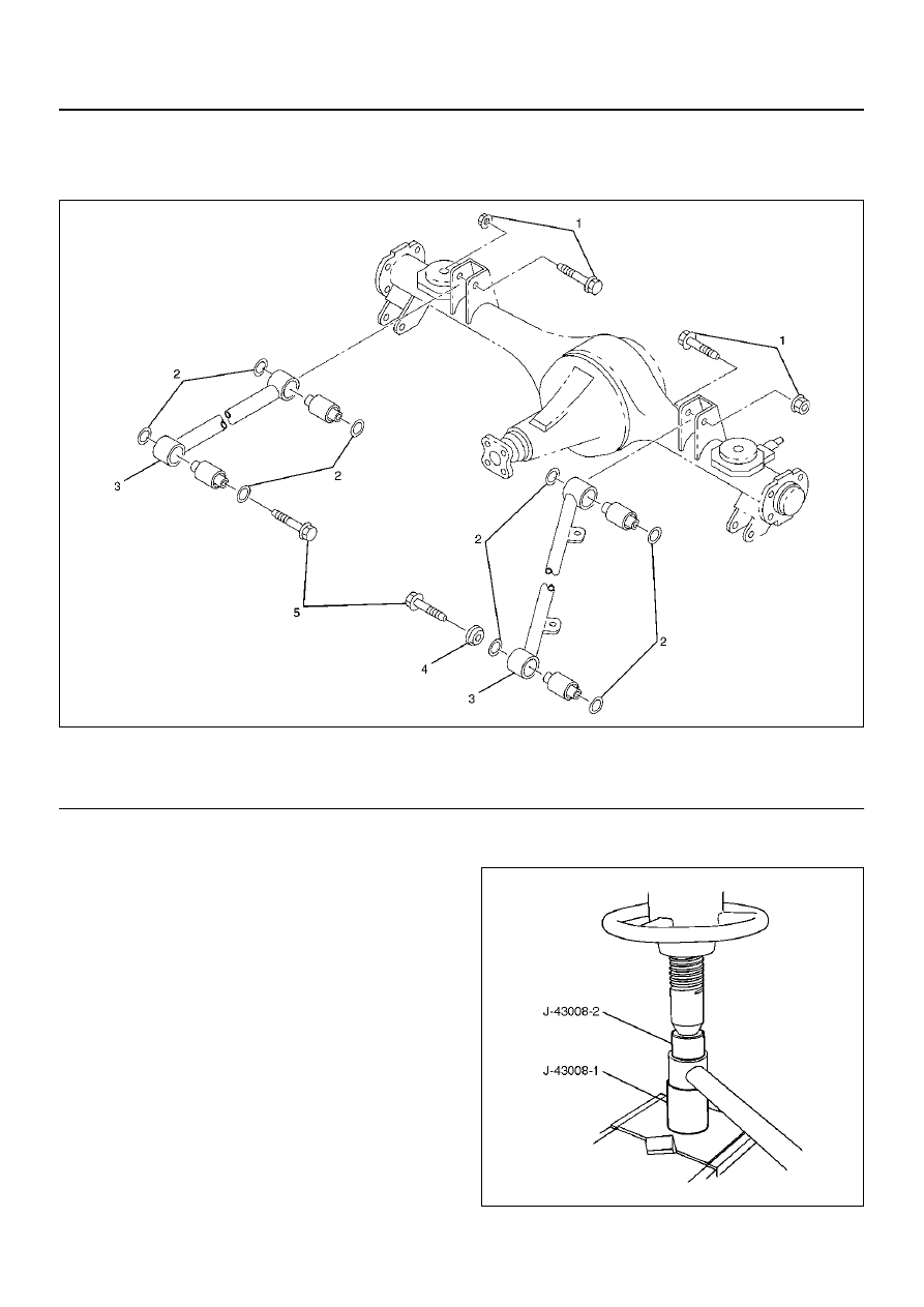
Upper Link and Associated Parts

460RW006

EndOFCallout

Removal

1. Remove fuel tank. Refer to Engine Fuel in Engine

section.

2. Remove the speed sensor cable from the upper link.

3. Remove bolt, nut, rubber plate and protector.

4. Remove upper link.

Inspection and Repair

Make necessary correction or parts replacement if wear,
damage, corrosion or any other abnormal condition are
found through inspection.

1. Upper link

2. Rubber bushing

• Remove the rubber bushing by using remover J–

43008.

460RY00006

Legend

(1) Bolt and Nut (Axle side)
(2) Rubber Plate

(3) Upper Link
(4) Protector (Left side only)
(5) Bolt (Frame side)

REAR SUSPENSION

3D–11

• Install the rubber bushing by using to installer J–

43008.

NOTE:  When mounting rubber bushings, be sure not to
use grease on bushings or any other nearby part.

460RY00007

Installation

1. Install upper link.  Make sure that the upper link is in

its correct position.

NOTE:  When mounting upper link, be sure not to use
grease bushings or any other nearby part.

460RW012

2. Install bolt, nut, rubber plate and protector.  Tighten

the bolts and nuts lightly, then retighten them to the
specified torque after the vehicle is at curb height.

Torque: 137 N·m (101 lb ft)

3. Install speed sensor cable.

4. Install fuel tank.

3D–12

REAR SUSPENSION

Lateral Rod

Lateral Rod and Associated Parts

460RW007

EndOFCallout

Removal

1. Remove nut and washer.

2. Remove bolt and nut.

3. Remove lateral rod.

Inspection and Repair

Make necessary correction or parts replacement if wear,
damage, corrosion or any other abnormal condition are
found through inspection.

1. Lateral rod 

2. Rubber bushing (Frame side)

• Remove the rubber bushing (Frame side) by

using remover J–39215.

901RW060

Legend

(1) Bolt and Nut (Frame side)

(2) Lateral Rod
(3) Nut and Washer (Axle side)

REAR SUSPENSION

3D–13

• Install the rubber bushing (Frame side) by using

Installer J–39215.

NOTE:  When mounting rubber bushings, do not use
grease on bushings or any other nearby parts.

901RW061

3. Rubber bushing (Axle side)

• Remove the rubber bushing (Axle side) by using

remover J–39792.

901RW062

• Install the rubber bushing (Axle side) by using

installer J–39792.

901RW063

Installation

1. Install lateral rod and make sure that the lateral rod

is in its correct position.

NOTE:  When mounting lateral rod, be sure not to use
grease on bushings or any other nearby part.

460RW008

EndOFCallout

2. Install bolt and nut (Frame side). Tighten the bolt

and nut lightly, then retighten them to the specified
torque after the vehicle is at curb height.

Torque: 137 N·m (101 lb ft)

3. Install nut and washer (Axle side). Tighten the nut

lightly, then retighten the nut to the specified torque
after the vehicle is at curb height.

Torque: 78 N·m (58 lb ft)

Legend

(1) Frame Side
(2) Axle Side


Content   ..  1110  1111  1112  1113   ..