Isuzu Amigo / Axiom / Trooper / Rodeo / VehiCross. Manual - part 40
2A–6 POWER–ASSISTED STEERING SYSTEM
Power Steering Pump
Foaming milky power steering fluid, low fluid level, and
possible low pressure can be caused by air in the fluid, or
loss of fluid due to internal pump leakage. Check for leak
and correct. Bleed the system. Extremely cold
temperatures will cause air bubbles in the system if the
fluid level is low. If the fluid level is correct and the pump
still foams, remove the pump from the vehicle and check
housing for cracks. If the housing is cracked, replace the
pump housing.
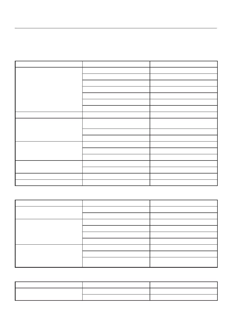
Condition
Possible cause
Correction
Low Pressure Due to Steering Pump
Relief valve sticking or inoperative.
Replace relief valve.
Side plate not flat against cam ring.
Replace side plate.
Extreme wear of cam ring.
Replace cam ring.
Scored side plate or rotor.
Replace side plate or rotor.
Vanes sticking in rotor slots.
Repair or replace vanes and rotor.
Cracked or broken side plate.
Replace side plate.
High internal leakage.
Repair internal leakage.
Low Pressure Due to Steering Gear
Scored housing bore.
Replace housing.
Growling Noise In Steering Pump
Excessive back pressure in hoses or
steering unit caused by restriction.
Repair steering unit or pump.
Scored side plate or rotor.
Replace side plate or rotor.
Worn cam ring.
Replace cam ring.
Groaning Noise In Steering Pump
Air in the fluid.
Bleed hydraulic system.
Low fluid level.
Replenish fluid.
Pump mounting loose.
Tighten mounting bolt.
Rattling Noise In Steering Pump
Vanes sticking in rotor slots.
Repair or replace vanes and rotor.
Vane improperly installed.
Repair rotor and vane.
Swishing Noise In Steering Pump
Damaged relief valve.
Replace relief valve.
Whining Noise In Steering Pump
Scored side plate and vanes.
Replace side plate and vanes.
Steering Column Lock System
Condition
Possible cause
Correction
Will Not Unlock
Damaged lock cylinder.
Replace lock cylinder.
Damaged park lock cable.
Replace park lock cable.
Will Not Lock
Lock spring broken or worn.
Replace lock cylinder.
Damaged lock cylinder.
Replace lock cylinder.
Ignition switch stuck.
Repair or replace ignition switch.
Park lock cable damaged.
Replace park lock cable.
Key Cannot be Removed in
“OFF LOCK”
Ignition switch is not set correctly.
Correct ignition switch.
“OFF-LOCK”
Damaged lock cylinder.
Replace lock cylinder.
Faulty shift lock mechanism.
Repair or replace the shift lock
mechanism.
Column
Condition
Possible cause
Correction
Noise in Column
Universal joint loose.
Tighten joint.
Shaft lock snap ring not seated.
Place snap ring in proper position.