Isuzu engine C22NE / 22LE / 20LE. Manual - part 76
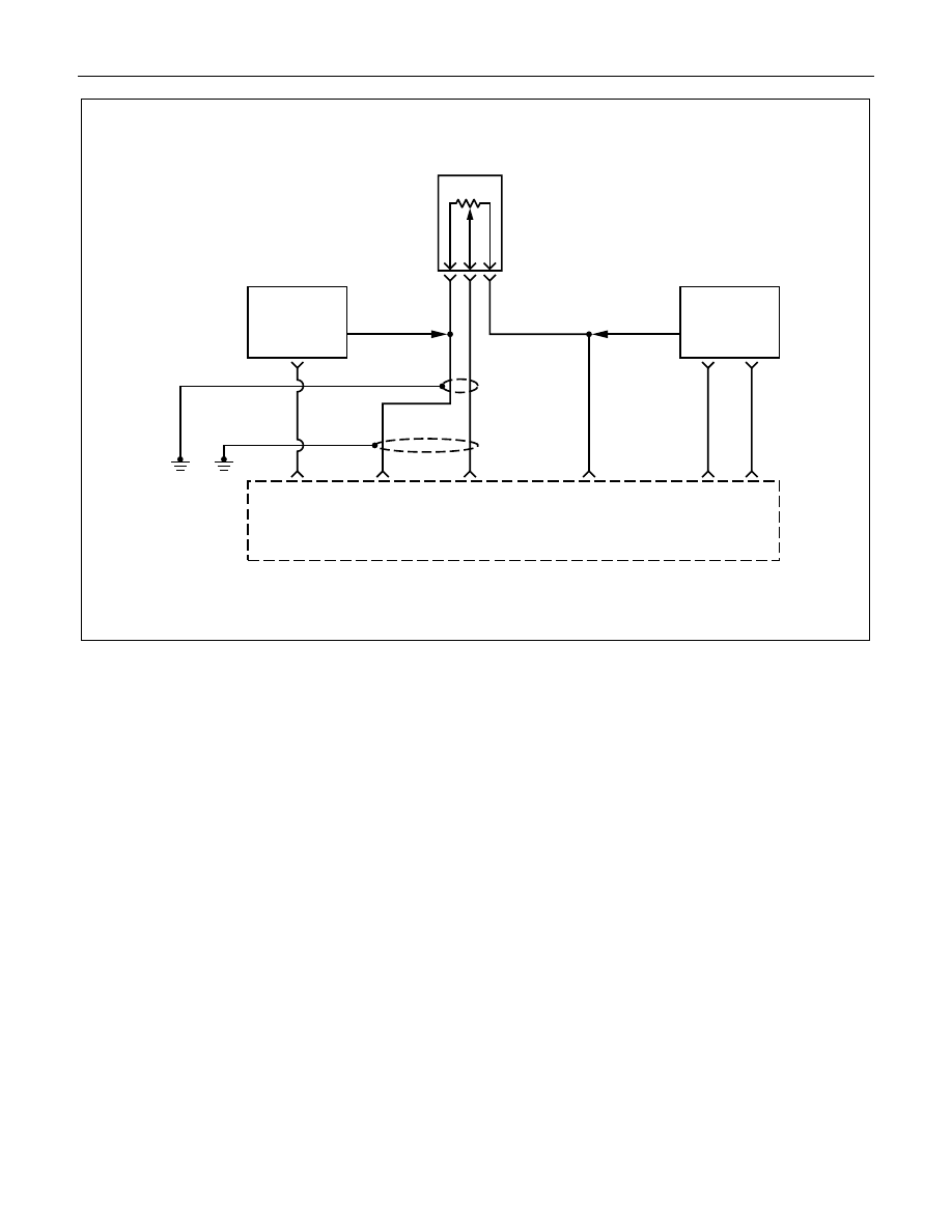
DRIVEABILITY AND EMISSIONS 6E1-133
0.5
R
0.5
G
0.5
GR
0.5
RED
0.75
GRN
0.75
L
0.5
GRN
Engine
Control
Module
(ECM)
F14
B1
A3
5 Volt
Reference
Signal
Throttle
Position
(TP)
Sensor
Input
Sensor
Ground
Sensor
Ground
B7
B2
Throttle
Position
(TP)
Sensor
B C
A
Manifold
Absolute
Pressure
Sensor
Engine
Coolant
Temperature
Sensor
B8
LO
HI
OUT
0.5
L/R
DIAGNOSTIC TROUBLE CODE (DTC) (Flash DTC = 22)
THROTTLE POSITION (TP) SENSOR CIRCUIT LOW INPUT
Circuit Description
The throttle position (Throttle Position) sensor circuit
provides a voltage signal that changes relative to
throttle blade angle. The signal voltage will vary from
below 1 volt at closed throttle to about 4 volts at wide
open throttle (WOT).
The Throttle Position signal is used by the engine
control module (ECM) for fuel control and most of the
ECM-controlled outputs. If the ECM detects a low
inpedance short to ground in the Throttle Position
sensor or circuit, then a code 22 will set.
Conditions for Setting the DTC
• Throttle Position sensor signal voltage is less than
0.19 volt.
Action Taken When the DTC Sets
• The ECM will illuminate the malfunction indicator
lamp (MIL) the first time the fault is detected.
• The ECM will use a default throttle position based
on RPM.
Conditions for Clearing the MIL/DTC
Once the ECM determines that a fault(s) has been
rectified then the CEL will switch OFF, although the
fault code will remain in the ECM memory.
Any fault codes will remain in ECM memory until -
1. They are cleared by disconnecting the Battery for
more than 30 seconds.
2. A service tool such as Tech 2 is used to clear them.
3. Ten consecutive starts without logging a fault.