Isuzu engine C22NE / 22LE / 20LE. Manual - part 72
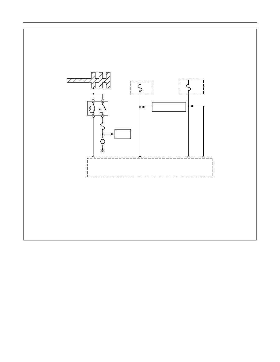
DRIVEABILITY AND EMISSIONS 6E1-117
A13
Fuel
Injectors
M
Battery Joint Cable
ECM
Fuse
15A
1.25
R/W
1.25
R/W
A4
A5
Engine
Fuse
15A
Canister Purge
Control Solenoid Valve
E16
Engine
Control
Module
(ECM)
Fuel
Pump
Relay
Fuel Pump Fuse
20A
0.5
P/W
0.85
B/Y
FUEL SYSTEM DIAGNOSIS
Circuit Description
When the ignition switch is turned ON, the engine
control module (ECM) will turn ON the in-tank fuel
pump. The in-tank fuel pump will remain ON as long
as the engine is cranking or running and the ECM is
receiving 58X crankshaft position pulses. If there are
no 58X crankshaft position pulses, the ECM will turn
the in-tank fuel pump OFF 2 seconds after the
ignition switch is turned ON or 2 seconds after the
engine stops running.
The in-tank fuel pump is an electric pump within an
integral reservoir. The in-tank fuel pump supplies fuel
through an in-line fuel filter to the fuel rail assembly.
The fuel pump is designed to provide fuel at a
pressure above the pressure needed by the fuel
injectors. A fuel pressure regulator, attached to the
fuel rail, keeps the fuel available to the fuel injectors
at a regulated pressure. Unused fuel is returned to
the fuel tank by a separate fuel return line.
Test Description
Number(s) below refer to the step number(s) on the
Diagnostic Chart.
2. Connect the fuel pressure gauge to the fuel feed
line as shown in the fuel system illustration. Wrap
a shop towel around the fuel pressure connection
in order to absorb any duel leakage that may