Isuzu engine C22NE / 22LE / 20LE. Manual - part 41
STARTING AND CHARGING SYSTEM 6D3-15
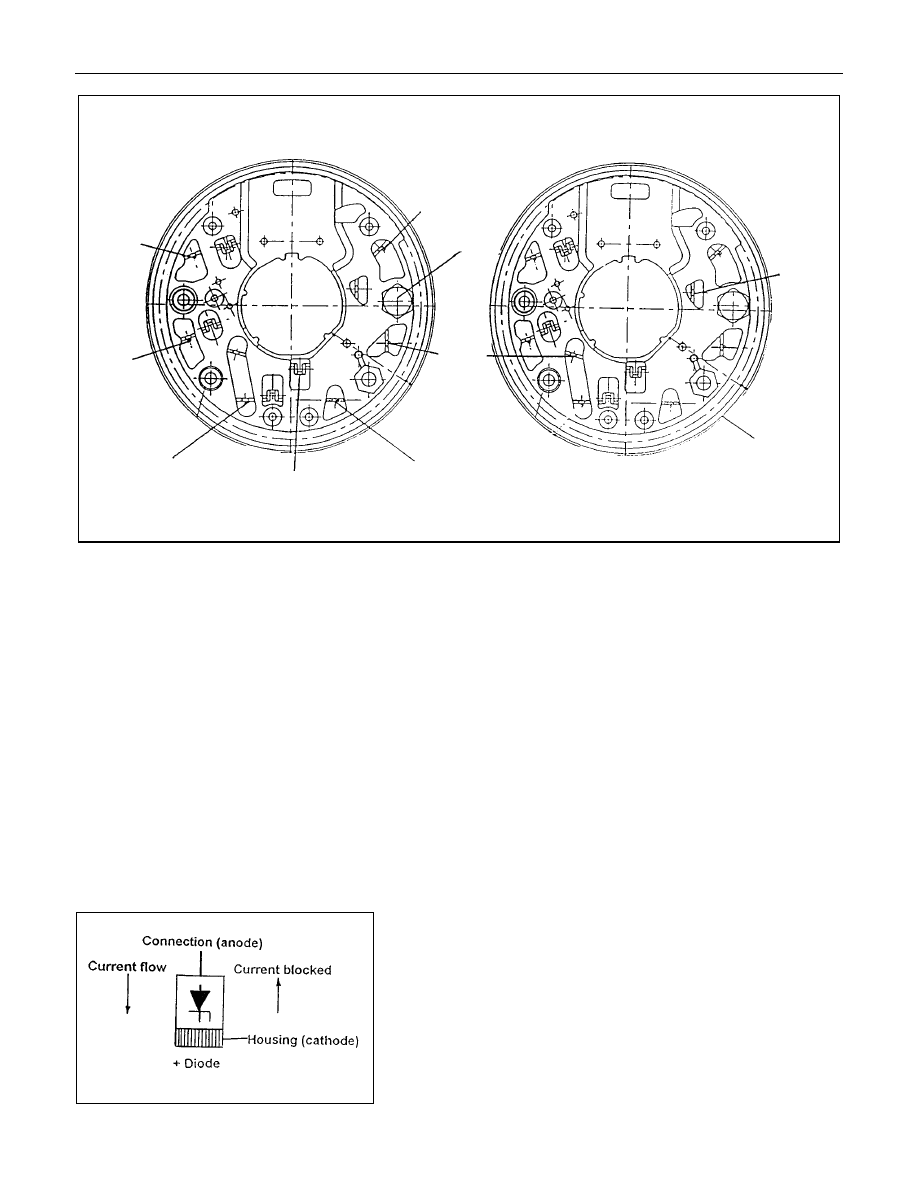
Positive heatsink
8 diode
6 diode
H
G
Negative heatsink
C
B
A
Starpoint
F
E
B+Bolt
D
Diode connections
Stator connection
1.1
Power Diodes.
Apply the negative test probe of the diode tester or a
multimeter with a diode test feature to the positive heatsink and
the positive probe alternatevely to A,B,C, a low resistance
reading, or the forward voltage drop across the diode shoud be
obtained. Reverse the test probes, a high resistance reading or
a higher reverse voltage should be obtained.
Now connect the positive test probe to the negative heatsink
and the negative alternatively to D,E,F, a low resistance or
forward voltage drop across the diode should be obtained.
Reverse the test probes, a high resistance reading or a higher
reverse voltage should be obtained.
For 8 diode rectifier plates tests for G and H should be
included. When the reverse voltage test is done the applied
voltage should be less than 14 volts DC or 12 volts RMS for
AC testers.
1.2
Zener Diode
The basic tests in 1.1 should be undertaken first before the
diode zener voltage is tested. Diodes are grouped together
according to their zener voltag i.e. all diodes within a rectifier
must have the same zener voltage.
Connect the test probes as for the reverese test listed above
i.e. reverse biased apply the test voltage form the zener diode
tester (current limited to 5ma) and read to zener breakdown
voltage this should be a steady reading and not increase with
increased voltage from the tester.