Content .. 1019 1020 1021 1022 ..
Isuzu Trooper (1998-2002 year). Manual - part 1021
8F–12
BODY STRUCTURE
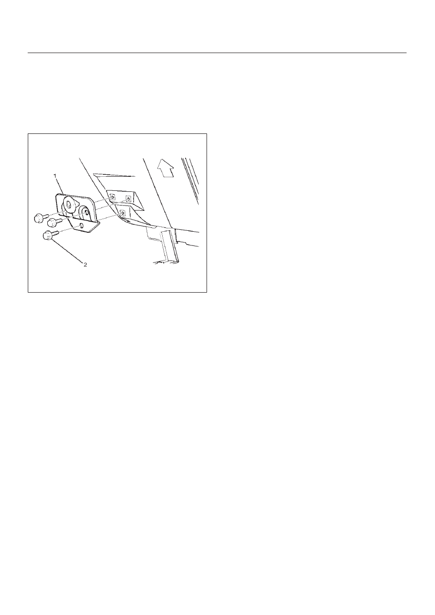
Rear Bumper Slider
Removal
1. Remove the rear bumper.
D
Refer to Rear Bumper removal in this section.
2. Remove the three bolts (2).
3. Remove rear bumper slider (1).
690RS004
Installation
To install, follow the removal steps in reverse order noting
the following points:
1. Apply chassis grease to the slider and the slider
bracket moving surface.