Isuzu N-Series. Manual - part 994
CAB AND CHASSIS ELECTRICAL 8-81
H-6, H-7, H-8
Neutral Switch
Refer to “START AND CHARGING” in this section.
Starter Relay
Refer to “START AND CHARGING” in this section.
Charge Relay
Refer to “START AND CHARGING” in this section.
Starter Switch
Refer to “START AND CHARGING” in this section.
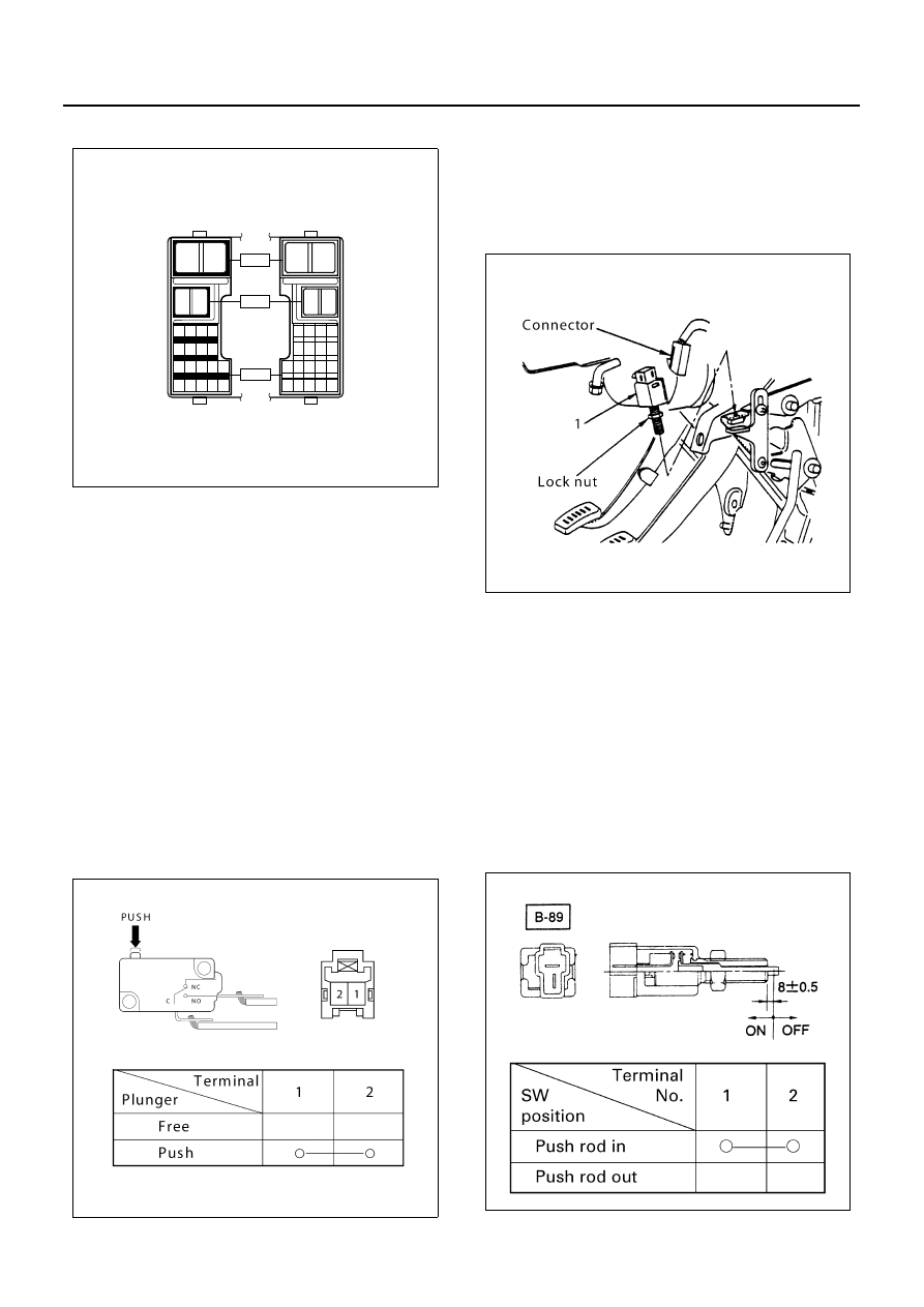
Accel Switch
Inspection
1. Check the continuity between the switch connector
terminals.
2. Check to see if switch plunger operates smoothly.
Repair or replace the accel switch when result of
inspection is found abnormal.
Removal
Preparation:
Disconnect the battery ground cable.
1. Accel Switch
1) Disconnect the connector.
2) Remove the two screws.
Installation
To install, follow the removal steps in the reverse order,
noting the following points.
1. Check to see if the accel pedal has been returned
by the return spring to the specified position.
Clutch Switch
Inspection
1. Check the continuity between the switch connector
terminals.
2. Check to see if switch push rod operates smoothly.
Repair or replace the switch when result of inspec-
tion is found abnormal.
1
2
1
2
1 2 3 4
5 6 7 8
9 10 11 12 13
14 15 16 17 18
2
1
2
1
4 3 2 1
8 7 6 5
13 12 11 10 9
18 17 16 15 14
H - 6
H - 7
H - 8
N8A5489E
N8A0087E
N8A0088E
N8A0089E