Isuzu N-Series. Manual - part 990
 

  Index      Isuzu     Isuzu N-Series - service repair manual


Search            


Content   ..  988  989  990  991   ..


Isuzu N-Series. Manual - part 990


CAB AND CHASSIS ELECTRICAL 8-65

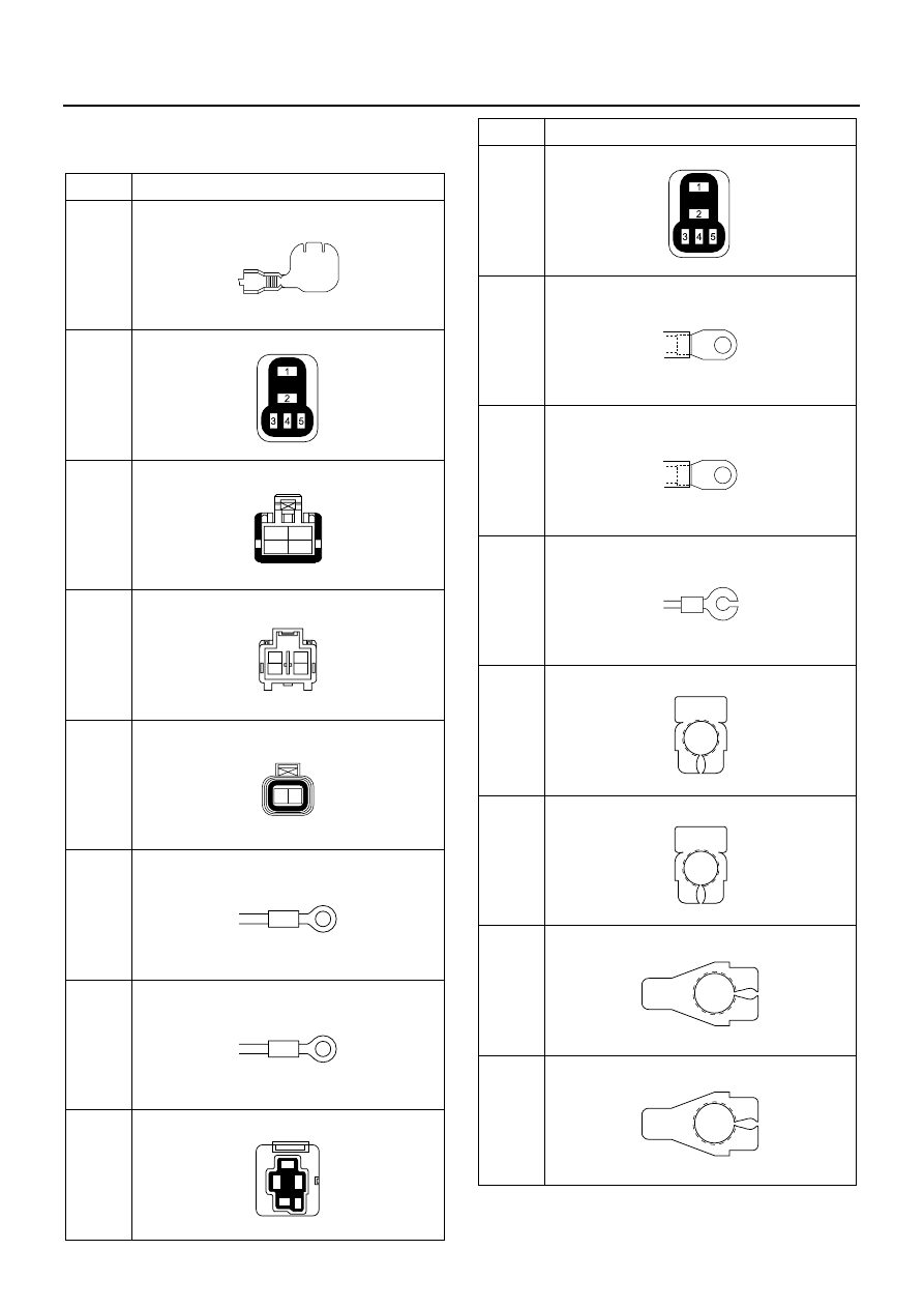
Connector List 

For 24 Volt

No.

Connector Face

B-7

X-1

B-67

B-67

J-1

J-2

J-9

X-21

000-012

005-006

004-001

1

2

3

4

004-002

2
4

1
3

002-003

1

2

000-001

000-001

005-003

1

2

3

5

4

X-26 
(N*R 

75)

J-26

P-5

J-27

P-1

P-4

P-2

P-3

No.

Connector Face

005-006

000-002

000-002

000-009

000-004

000-004

000-006

000-006

8-66 CAB AND CHASSIS ELECTRICAL

H-5

H-6, H-7, H-8

Starter Switch

The starter switch positions are LOCK, ACC, ON and
START. Turning the starter key to these positions a cir-
cuit for starting the engine, the operation of accessories,
or stop the engine.

P-6 

(N*R 

66)

No.

Connector Face

000-008

1

2

3

7

8

9

13

14 15

19

20 21

25

26 27

31

32 33

34

35

36

37

4

5

6

10

11 12

16

17 18

22

23 24

28

29 30

38

39 40

6

5

4

12

11 10

18

17 16

24

23 22

30

29 28

40

39 38

3

2

1

9

8

7

15

14 13

21

20 19

27

26 25

33

32 31

34

35

36

37

N8A5488E

1

2

1

2

1 2 3 4

5 6 7 8

9 10 11 12 13

14 15 16 17 18

2

1

2

1

4 3 2 1

8 7 6 5

13 12 11 10 9

18 17 16 15 14

H - 6

H - 7

H - 8

N8A5489E

N8A0072E

CAB AND CHASSIS ELECTRICAL 8-67

Inspection
Check the continuity between the starter switch connector terminals.
Repair or replace the switch when the result of inspection is found abnormal.

Removal
Preparation:
Disconnect the battery ground cable.

1. Steering Cowl

Remove four screws and take off the steering cowl.

2. Starter Switch

1) Disconnect the connector.
2) Remove the screw.

N8A0073E

N8A0074E

8-68 CAB AND CHASSIS ELECTRICAL

QOS (Quick On Start) II System (4HF1 and 4JB1 Engine Model)

General Description

The circuit consists of starter switch, QOSII control unit, glow relay, thermo switch, glow plug, fuel cut solenoid, CSD
relay, CSD solenoid and glow indicator light.
The QOS-II controller controls glow plug relay by the ON or OFF signal of QOS thermo switch.
Immediately when the starter switch turns “ON”, the glow plug relay indicator light turns on to start preheating.
The engine should be started after the indicator light is off. However, the glow plug relay keeps preheating for a fixed
period even after the indicator light turns off. When the fixed time is over, QOS-II controller performs to switch the
glow plug relay off to stop preheating.
For details, refer to “PREHEATING SYSTEM”.

System Circuit

N8A0075E


Content   ..  988  989  990  991   ..