Isuzu N-Series. Manual - part 893


  Index      Isuzu     Isuzu N-Series - service repair manual


Search            


Content   ..  891  892  893  894   ..


Isuzu N-Series. Manual - part 893


Transmission Control System (Smoother) 7A-27
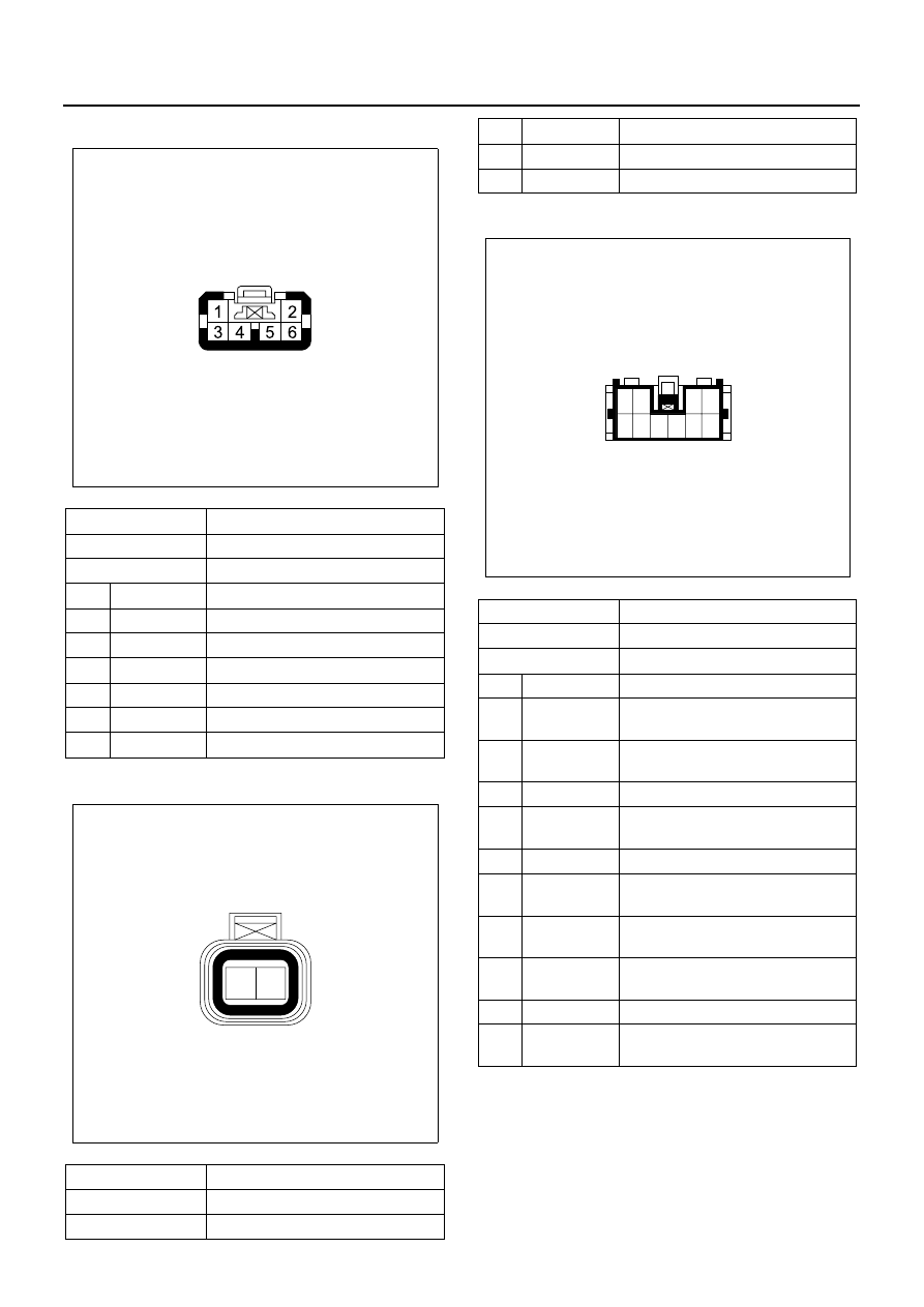
Reset Switch

Select Solenoid

Selector Lever

Connector No.

B-105

Connector Color

Black

Test Adapter No.

J-35616-4A

Pin 

Wire Color

Pin Function

1

Not Used

2

Not Used

3

Not Used

4

BLK/ORN

Reset Switch Voltage Feed

5

Not Used

6

GRY/BLU

Reset Switch Signal

Connector No.

J-234

Connector Color

Green

Test Adapter No.

J-35616-42

N7A2113E

1

2

N7A2103E

Pin Wire 

Color

Pin 

Function

1

BLK

Select Solenoid Valve Ground

2

WHT/BLK

Select Solenoid Valve Control

Connector No.

N-19

Connector Color

White

Test Adapter No.

J-35616-33

Pin Wire 

Color

Pin 

Function

1

LT GRN/ 

RED

Illumination Lamp Voltage Feed

2

RED/BLK

Selector Lever “R” Position Switch
Signal

3

YEL/RED

1st Gear Start Switch Signal

4

GRN/BLK

Selector Lever “A” Position Switch
Signal

5

BLU

Economy Mode Switch Signal

6

WHT/BLK

Selector Lever “N” Position Switch
Signal

7

ORN

Selector Lever “D” Position Switch
Signal

8

PNK/BLK

Selector Lever “

−” Position Switch

Signal

9

BLK

Selector Lever Ground

10

BLU/BLK

Selector Lever “+” Position Switch
Signal

10

9

8

7

6

5

4

3

2

1

N7A2115E

7A-28 Transmission Control System (Smoother)

Solenoid Valves & Transmission Fluid Temperature
Sensor In-line Harness Connector

Turbine Speed Sensor

Connector No.

J-237

Connector Color

Gray

Test Adapter No.

J-35616-33

Pin 

Wire Color

Pin Function

1

RED/YEL

Lock Up Clutch Solenoid Valve
Control

2

YEL/RED

Transmission Fluid Temperature
Sensor Signal

3

YEL/BLK

Gearshift Clutch Solenoid Valve
Control

4

BLU/WHT

Transmission Fluid Temperature
Sensor Low Reference

N7A2116E

N7A2110E

Connector No.

J-232

Connector Color

Gray

Test Adapter No.

J-35616-33

Pin Wire 

Color

Pin 

Function

1

ORN/BLU

Turbine Speed Sensor Low
Reference

2

WHT/BLU

Turbine Speed Sensor Signal

Transmission Control System (Smoother) 7A-29

Diagnostic Information and Procedures

General Service Information

Non-OEM Parts

All of the on-board diagnostic (OBD) has been
calibrated to run with original equipment manufacturer
(OEM) parts. Accordingly, if commercially sold sensor or
switch is installed, it makes a wrong diagnosis and turn
on the transmission warning lamp. Aftermarket
electronics, such as cellular phones, stereos, and anti-
theft devices, may indicate electromagnetic interference
(EMI) into the control system if they are improperly
installed. This may cause a false sensor reading and
turn on the transmission warning lamp. 

Poor Vehicle Maintenance

The sensitivity of OBD will cause the transmission
warning lamp turn on if the vehicle is not maintained
properly. Restricted oil filters, fuel filters, and crankcase
deposits due to lack of oil changes or improper oil
viscosity can trigger actual vehicle faults that were not
previously monitored prior to OBD. Poor vehicle
maintenance cannot be classified as a “non-vehicle
fault”, but with the sensitivity of OBD diagnostics, vehicle
maintenance schedules must be more closely followed.

Visual/Physical Transmission Compartment
Inspection

Perform a careful visual and physical transmission
compartment inspection when performing any
diagnostic procedure or diagnosing the cause of an
emission test failure. This can often lead to repairing a
problem without further steps. Use the following
guidelines when performing a visual/physical
inspection:

• Inspect all vacuum hoses for punches, cuts,

disconnects, and correct routing.

• Inspect hoses that are difficult to see behind other

components.

• Inspect all wires in the transmission compartment

for proper connections, burned or chafed spots,
pinched wires, contact with sharp edges or contact
with hot exhaust manifolds or pipes.

Basic Knowledge of Tools Required

Lack of basic knowledge of this powertrain when
performing diagnostic procedures could result in an
incorrect diagnosis or damage to powertrain
components. Do not attempt to diagnose a powertrain
problem without this basic knowledge. A basic
understanding of hand tools is necessary to effectively
use this section of the service manual.

Transmission Warning Lamp

Basically, the transmission warning lamp is turned on
when the transmission control module (TCM) detects a
DTC that will impact the vehicle performance. When the
transmission warning lamp remains “ON” while the
engine is running, or when a malfunction is suspected
due to a driveability problem, a Diagnostic System
Check must be performed. The procedures for these
checks are given in Diagnostic System Check -
Transmission Controls.

Reading Flash Diagnostic Trouble Codes (DTC)

The provision for communicating with the TCM is the
Data Link Connector (DLC). The DTCs stored in the
TCM memory can be read either through a hand-held
diagnostic scanner such as Tech 2 plugged into the DLC
or by counting the number of flashes of the transmission
warning lamp when the diagnostic test terminal of the
DLC is grounded. The DLC terminal “11” (diagnostic
request) is pulled “Low” (grounded) by jumped to DLC
terminal “4”, which is a ground wire. Once terminals “11”
and “4” have been connected, the ignition switch must
be moved to the “ON” position, with the engine not
running. The transmission warning lamp will indicate a
DTC three times is a DTC is present and history. If more
than one DTC has been stored in the TCM’s memory,
the DTCs will be output numerical order with each DTC
being displayed three times. The flash DTC display will
continue as long as the DLC is shorted.

Notice:

• If DTC is present, buzzer also sounds with a lamp

illumination. 

• When present DTC and history DTC are mixed,

present DTC is always output first, regardless of
number of DTC.

7A-30 Transmission Control System (Smoother)

Reading Diagnostic Trouble Codes (DTCs) with
The Tech 2

The procedure for reading DTC(s) is used a diagnostic
Tech 2. To read DTCs, use the Tech 2 “Read DTC Info
As Stored By ECU”. 

Clearing Diagnostic Trouble Codes (DTCs) with
The Tech 2 or without Tech2

Do not clear DTCs unless directed to do so by the
service information provided for each diagnostic
procedure. To clear DTCs, use with the Tech 2 “Clear
DTC Information”. If there is no Tech 2, clear with reset
switch operation. 

DTC Clear Method with Reset Switch Operation

1. Turn ON the ignition, with the engine OFF.
2. Use a jumper wire and the DLC terminal “11”

(diagnostic request) is pulled “Low” (grounded) by
jumped to DLC terminal “4”.

3. Press reset switch for at least 1 second and

release it within 6 seconds.

4. If completed, buzzer will sound with a short beep.

Notice:
If the buzzer does not sound, restart clear procedure
from step 1.

Tech 2 Scan Tool

Isuzu recommend using Tech 2. Refer to the Tech 2
Users Guide for proper start up procedures.

Operating Procedure

1. Press Enter at start screen.
2. Select Diagnostic > appropriate vehicle

identification > Transmission > Smoother.

3. The following table shows, which functions are

used the available equipment versions.

F0: Diagnostic Trouble Codes
The purpose of this mode is to display stored trouble
code in the TCM. When “Clear DTC Information” is
selected, “Clear DTC Information”, warning screen
appears. This screen informs you that by cleaning DTCs
“all stored DTC information in the TCM will be erased”.
F1: Data Display
The purpose of this mode is to continuously monitor
data parameters. The current actual values of all
important sensors and signals, solenoid commands in
the system are display through this mode. 
Refer to the “Tech 2 Data List” in this section.
F2: Snapshot
“Snapshot” allow you to focus on making the condition
occur, rather than trying to view all of the data in
anticipation of the fault. The snapshot will collect
parameter information around a trigger point that you
select. 
Refer to the Tech 2 user instructions for more
information.

Example: DTC 24 stored

ON

OFF

2.4

0.6

0.6

0.6

0.6

2.4

0.3

0.3

0.3

1.2

1.2

Unit: second

2nd digit number

0.6

1st digit number

0.3

0.6

0.6

2

4

N7A2118E

F0:  Diagnostic Trouble Codes

F0:  Read DTC Info As Stored By ECU

F1:  Clear DTC Information

F1:  Data Display

F2:  Snapshot

F3:  Programming

F0:  Program Vehicle Type

F1:  PTO Requested Engine Speed

F2:  Program Speedometer Driven Gear

N7A2119E


Content   ..  891  892  893  894   ..