Isuzu N-Series. Manual - part 861


  Index      Isuzu     Isuzu N-Series - service repair manual


Search            


Content   ..  859  860  861  862   ..


Isuzu N-Series. Manual - part 861


MANUAL TRANSMISSION 7B-105

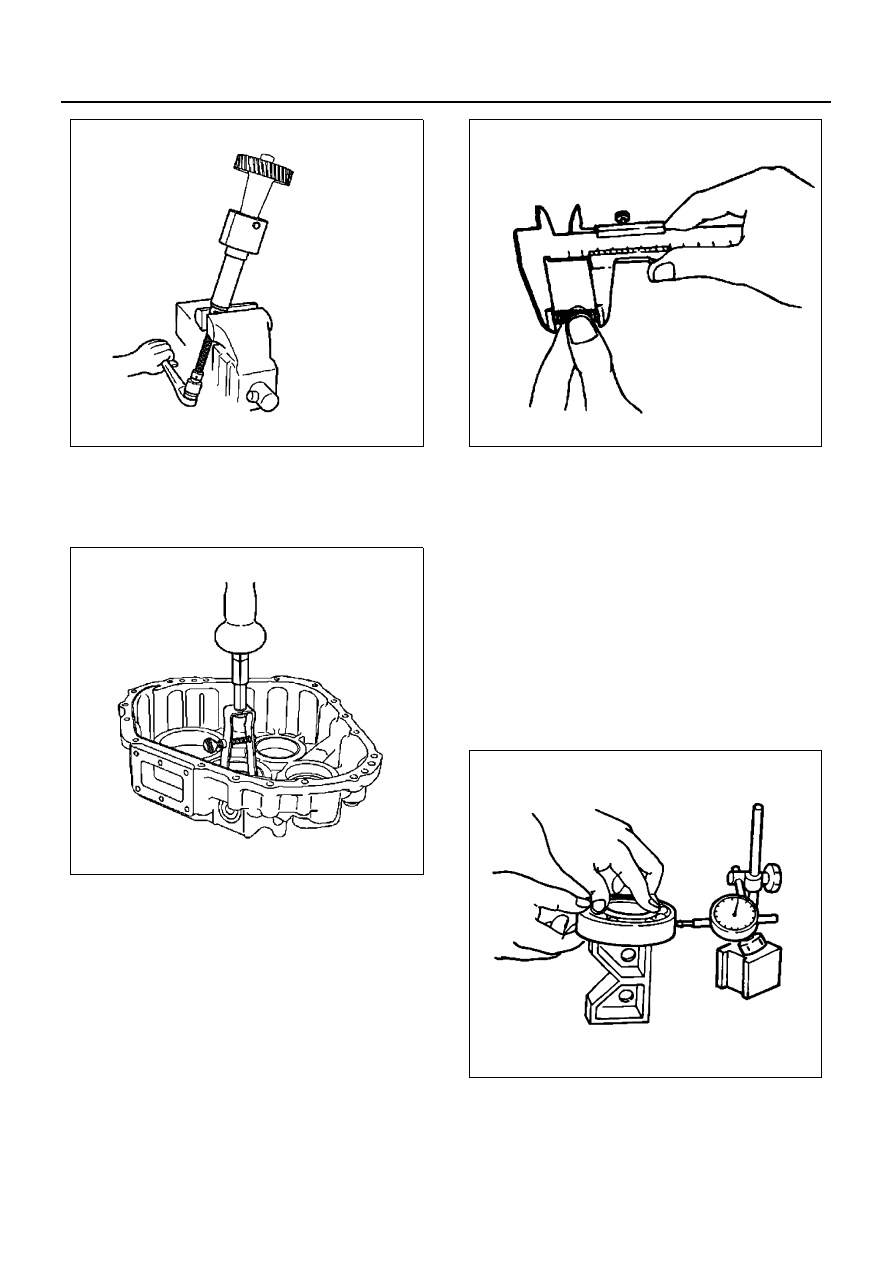
22. Remove the bearing outer race of the idle gear

shaft.

• Remove using the bearing race remover 5-

8840-0027-0.

Assembly

1. Clean and inspect the disassembled parts. If any

abnormality including wear, damage or corrosion is
found, repair or replace the part.

• Measure the free length of the detent spring.

Free Length of Detent Spring
Standard: 31.6 mm (1.244 in)    Limit: 30.1 mm (1.185 in)

• Inspect each bearing. If any abnormality is

found, replace the bearing.

– Smoothness of rotation
– Noise
– Abnormal external appearance, including

damage or rust

– Abnormal free play in thrust direction
– Discoloration, excessive wear and pitching

of rotating body and rotating surface of nee-
dle bearing

• Measure the free play in the radial direction of

the ball bearing.

Free play in the radial direction of the ball bearing
Limit: 0.2 mm (0.0079 in)

• Inspect the sleeve sliding surface of the shift

arm. Check that there is no excessive wear or
damage.

• Inspect the gear. Repair slight stepped surface

or roughness using an oil stone or pencil grind-
er.

N7A0461E

N7A0462E

N7A0424E

N7A0426E

7B-106 MANUAL TRANSMISSION

– Damage on tooth surfaces
– Excessive wear of tooth surfaces
– If excessive wear or damage is found on the

tooth surfaces of the dog clutch, replace the
part.

• Oil seal

– Replace the removed oil seal with a new

one.

2. Bearing shim adjustment

• Adjust the thickness of the shim of the rear out-

put shaft rear bearing, using the shim selector
5-8840-0194-0 and shim selector adaptor 5-
8840-2794-0.

• Measure the thickness of the shim, using the

gauge pin J-35824-8 (1), gauge cylinder J-
35824-31(2), bridge assembly J-35824-1(3),
extension J-35824-19(4) and spacer J-35824-
30(5) included in the shim selector gauge and
the shim selector set.

a. Loosen the screw, put the gauge cylinder on

the rear bearing edge surface of the output
shaft, and fix with the screw.

b. Remove the leg and spacer from the bridge. In-

stall the extension (4) to the bridge to enable
the bridge to connect to the rear transfer case
mating surface.

c. Turn the bridge assembly upside down, and

then set the bearing assembly to the installa-
tion hole surface of the output shaft rear bear-
ing of the mating side rear transfer case.

d. Loosen the screw, put the gauge pin (1) on the

bearing installation surface, and fix the screw.

e. Measure the clearance between the gauge cyl-

inder and the gauge pin, and select the size of
the shim. Adjustment to the standard end plate
0 — 0.05 mm (0 — 0.002 in) becomes possible.

• Set the selected shim on the bearing surface

of the bearing race, and press in the race. 

• Adjust the shim for the bearing outer of the

idle shaft in the same manner.

N7A0463E

N7A0464E

N7A0429E

MANUAL TRANSMISSION 7B-107

3. Install the oil seals of the rear output shaft, front

output shaft and input shaft.

• Apply engine oil on the outer circumference of

a new oil seal, and apply grease (Besco L2 or
equivalent) to the lip part.

• Install the rear output oil seal using the installer

5-8840-2775-0.

• Install the front output oil seal using the installer

5-8840-2774-0.

• Install the input oil seal using the installer 5-

8840-2776-0.

Caution:
Make sure to install the inner side and outer side of the
input shaft oil seal from the transmission side.

• Installation direction of the inner side oil seal of

the input shaft is indicated.

• Installation direction of the outer side oil seal of

the input shaft is indicated.

• Install the oil seal of the 2WD / 4WD change

shift rod part of the rear transfer case.

• Install the front output shaft oil seal to the front

transfer case.

Installation Position

Shims, which can be selected, mm (in)

Idle gear shaft

0.18 (0.0070)

Rear output gear shaft

0.25 (0.0098)

0.30 (0.0118)

0.35 (0.0137)

0.40 (0.0157)

0.50 (0.0196)

N7A0465E

Legend

1. Input shaft oil seal
2. Rear output shaft oil seal
3. Shift rod oil seal
4. Front output shaft oil seal

N7A0466E

N7A0467E

7B-108 MANUAL TRANSMISSION

4. Press in the bearing outer race of the idle gear

shaft and rear output gear shaft.

• Use the installer 5-8840-2773-0 and the grip 5-

8840-0007-0 to press in the front side outer
race of the idle gear shaft.

• Use the installer 5-8840-2235-0 and the grip 5-

8840-0007-0 to press in the rear side outer race
of the idle gear shaft.

• Use the installer 5-8840-2772-0 and the grip 5-

8840-0007-0 to press in the front & rear side
outer race of the rear output gear shaft.

5. Install the front & rear bearing inner race of the idle

gear shaft.

• Use a press machine to press in the roller bear-

ing.

6. Assemble the front output gear shaft.

• Before installing the ball bearing, install the

needle bearing, front output drive gear, thrust
washer and collar.

• Use a press machine to press in the ball bear-

ing.

• After installing the ball bearing, install the

sleeve in accordance with the marked direc-
tion.

Caution:
Make sure to install in the correct direction.

7. Assemble the input gear shaft.

• Before installing the front side ball bearing, in-

stall the needle bearing, transfer low gear and
thrust washer.

• Before installing the rear side ball bearing, in-

stall the sleeve, needle bearing, transfer high
gear and thrust washer.

Caution:
Install the sleeve by turning the side, which has a groove
along its outer circumference, toward the front side.

• Use a press machine to press in the ball bear-

ing.

N7A0468E

N7A0469E

N7A0470E

N7A0471E


Content   ..  859  860  861  862   ..