Isuzu N-Series. Manual - part 839


  Index      Isuzu     Isuzu N-Series - service repair manual


Search            


Content   ..  837  838  839  840   ..


Isuzu N-Series. Manual - part 839


MANUAL TRANSMISSION 7B-17
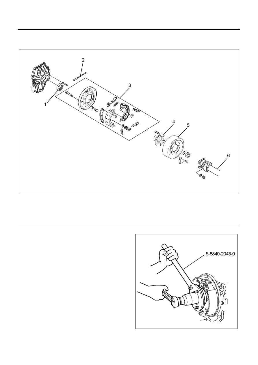
Rear Oil Seal (5MT)

Components

Removal

1. Remove the rear propeller shaft assembly.

• Refer to REAR PROPELLER SHAFT ASSEM-

BLY.

2. Remove the parking brake cable.

• Refer to PARKING BRAKE CABLE.

3. Remove the parking brake drum.

• Refer to PARKING BRAKE ASSEMBLY.

4. Remove the coupling driver and O-ring.

• Raise the lock nut caulking portion (two parts)

securely, and then remove the lock nut using
the flange holder 5-8840-2043-0.

5. Remove the parking brake assembly.

• Refer to PARKING BRAKE ASSEMBLY.

Legend

1. Oil seal

4. Coupling driver

2. Parking brake cable

5. Parking brake drum

3. Parking brake assembly

6. Rear propeller shaft assembly

N7A0293E

N7A0294E

7B-18 MANUAL TRANSMISSION

6. Remove the rear oil seal using the flat-tip screw-

driver.

Installation

1. Apply engine oil 5W-30 around a new oil seal, and

then press in the oil seal to the rear cover using the
installer 5-8840-2750-0.

• Apply Besco L2 grease on the lip of the oil seal.

Caution:
Be careful not to damage the lip of the oil seal.

2. Install the parking brake assembly.

• Refer to PARKING BRAKE ASSEMBLY.

3. Install the coupling driver.

a. Apply engine oil 5W-30 to the O-ring, and then

install the coupling driver and the O-ring.

b. Use a new lock nut and apply engine oil 5W-30

on its seat, and then fix the lock nut using the
flange holder 5-8840-2043-0.

Tighten:
Lock nut to 289 N

⋅m (29.5 kg⋅m / 213 lb⋅ft)

• After fixing it to the specified torque, align the lip

part of the nut to the V-groove of the shaft edge.
Securely caulk the two parts of the nut lip using
a chisel whose tip form is approx. 1 mm (0.04
in) radius by 60

°, to make a length (B) of 5 mm

(0.2 in) or more, and a clearance between the
bottom of the shaft and the nut lip (A) of 1.5 mm
(0.06 in) or less.

Caution:
If any crack is found on the caulking portions of the nut
after the check, replace the lock nut and caulk it again.

N7A0295E

N7A0294E

MIN
5.0mm

MIN
5.0mm

MAX
2.5mm

MAX
2.5mm

A

B

N7A0297E

MANUAL TRANSMISSION 7B-19

4. Install the parking brake drum.

• Refer to PARKING BRAKE ASSEMBLY.

5. Install the parking brake cable.

• Refer to PARKING BRAKE CABLE.

6. Install the rear propeller shaft assembly.

• Refer to REAR PROPELLER SHAFT ASSEM-

BLY.

Fixing Torque

Special Tools

N7A0298E

Illustration

Tool Number / 

Description / Remarks

5-8840-2043-0 / Flange 

Holder

5-8840-2750-0 / Oil Seal 

Installer

5884020430

5884027500

7B-20 MANUAL TRANSMISSION

Rear Oil Seal (6MT)

Components

Removal

1. Remove the rear propeller shaft assembly.

• Refer to REAR PROPELLER SHAFT ASSEM-

BLY.

2. Remove the parking brake cable.

• Refer to PARKING BRAKE CABLE.

3. Remove the parking brake drum.

• Refer to PARKING BRAKE ASSEMBLY.

4. Remove the coupling driver and O-ring.

• Raise the caulking portion (2 parts) of the lock

nut securely, and remove it using the flange
holder 5-8840-2043-0.

5. Remove the parking brake assembly.

• Refer to PARKING BRAKE ASSEMBLY.

Legend

1. Oil seal

4. Coupling driver

2. Parking brake cable

5. Parking brake drum

3. Parking brake assembly

6. Rear propeller shaft assembly

N7A0299E

N7A0294E


Content   ..  837  838  839  840   ..