Isuzu N-Series. Manual - part 803


  Index      Isuzu     Isuzu N-Series - service repair manual


Search            


Content   ..  801  802  803  804   ..


Isuzu N-Series. Manual - part 803


 Engine Control System (4JH1)    6E-263

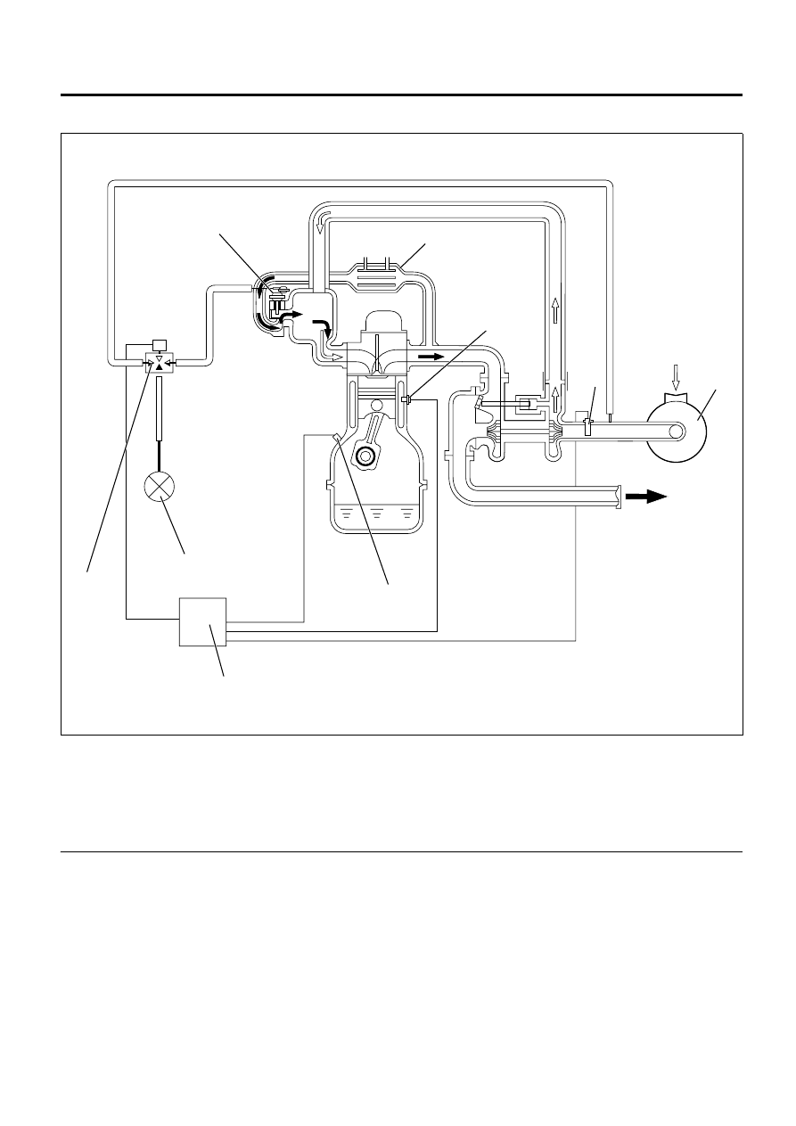
Exhaust Gas Recirculation (EGR) System Description

Legend

1. EGR Valve
2. EGR Cooler
3. ECT Sensor
4. MAF & IAT Sensor
5. Air Cleaner

6. CKP Sensor
7. ECM
8. EGR Solenoid Valve
9. Vacuum Pump


The EGR system recirculates a part of exhaust gas
back into the intake manifold, which results in reducing
nitrogen oxide (NOx) emissions.  The EGR control
system uses an electronic control system solenoid
valve and vacuum control EGR valve to ensure both
driveability and low emission.  The engine control
module (ECM) controls the EGR flow amount based on
the engine speed, engine coolant temperature, intake
air temperature, barometric pressure and fuel injection
quantity.  The ECM controls the EGR valve opening by
controlling the EGR solenoid valve drive duty.  The
mass air flow (MAF) sensor monitors EGR gas flow

amount.  An expected MAF amount should be detected
while the engine running.

5

7

8

9

6

4

1

2

3

N6A3890E

6E-264    Engine Control System (4JH1) 

Turbocharger Description

Legend

1. Exhaust Gas
2. Waste Gate Valve
3. Turbine Wheel
4. Compressor Wheel
5. Air Cleaner
6. Charge Air Cooler (Intercooler)


The turbocharger is used to increase the amount of air
that enters the engine cylinders.  This allows a
proportional increase of fuel to be injected into the
cylinders, resulting in increased power output, more
complete combustion of fuel, and increased cooling of
the cylinder heads, pistons, valves, and exhaust gas.
This cooling effect helps extend engine life.
Heat energy and pressures in the engine exhaust gas
are utilized to drive the turbine.  Exhaust gas is directed
to the turbine housing.  The turbine housing acts as a
nozzle to direct the shaft wheel assembly.  Since the
compressor wheel is attached directly to the shaft, the
compressor wheel rotates at the same speed as the
turbine wheel.  Clean air from the air cleaner is drawn
into the compressor housing and wheel.  The air is
compressed and delivered through a crossover pipe to
the engine air intake manifold, then into the cylinders.
The amount of air pressure rise and air volume
delivered to the engine from the compressor outlet is
regulated by a waste gate valve in the exhaust housing.
The position of the waste gate valve is controlled by the
amount of pressure built up on the intake side of the
turbocharger.  The diaphragm on the inside of the
waste gate is pressure sensitive, and controls the
position of the valve inside the turbocharger.  The
position of the valve will increase or decrease the
amount of boost to the turbocharger.

The charge air cooler also helps the performance of the
diesel.  Intake air is drawn through the air cleaner and
into the turbocharger compressor housing.
Pressurized air from the turbocharger then flows
forward through the charge air cooler located in the
front of the radiator.
From the charge air cooler, the air flows back into the
intake manifold.
The charge air cooler is a heat exchanger that uses air
flow to dissipate heat from the intake air.  As the
turbocharger increases air pressure, the air
temperature increases.  Lowering the intake air
temperature increases the engine efficiency and power
by packing more air molecules into the same space.

1

3

2

4

5

6

N6A3891E

 Engine Control System (4JH1)    6E-265

Special Tools and Equipment

Special Tools and Equipment

Illustration

Tool Number / Description

5-8840-2835-0 (J-35616-A)

Connector Test Adapter Kit 

(With Test Lamp)

5-8840-0285-0 (J-39200)

Digital Multimeter


Tech 2 Kit


Breaker Box


Adapter Harness

5-8840-0607-0 (J-34142-B)

Test Lamp

5884028350

5884002850

7000081

A

B

C

5884006070

5-8840-0279-0 (J-23738-A)

Vacuum Pump

Illustration

Tool Number / Description

5884002790

International Service & Parts

Tokyo,  Japan

WORKSHOP MANUAL

N-SERIES

MANUAL TRANSMISSION AND 

CLUTCH MSB SERIES

SECTION 7


Content   ..  801  802  803  804   ..