Isuzu N-Series. Manual - part 635


  Index      Isuzu     Isuzu N-Series - service repair manual


Search            


Content   ..  633  634  635  636   ..


Isuzu N-Series. Manual - part 635


ENGINE ELECTRICAL 6D-33

Reassembly of Vacuum Pump

1. Position the rotor, with the serrated boss turned up,

on the center plate and housing.
Align the holes in center plate and rotor.

2. Install vanes into slits in rotor.

The vanes should be installed with chamfered side
turned outward.

3. Install the O-ring and center plate
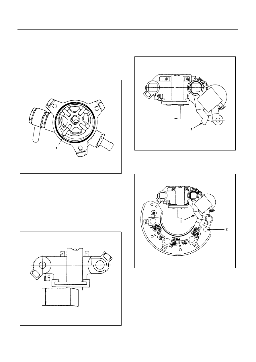
Reassembly

1. Brush Holder
2. IC Regulator Assembly

• Hold the brush in the holder as shown in the il-

lustration and solder the lead wire.

• Put the IC regulator on the brush holder and

press the bolt.
Bushing and connecting plate (1) must be in-
stalled when pressing the bolt.

3. Diode

• Connect the terminals by fixing the rivet at (1)

and soldering the terminal at (2).

4. Stator

• When connecting stator coil leads and diode

leads using solder, use long-nose pliers and
finish the work as quickly as possible to prevent
the heat from being transferred to the diodes.

Legend

1. Chamfered side

N6A3547E

N6A3548E

N6A3549E

N6A3550E

6D-34 ENGINE ELECTRICAL

5. Rear Cover
6. Terminal Bolt and Nut
7. Rear Bearing
8. Rotor

• Cover vice with copper plates, clamp the rotor

with the vice, and tighten nut to the specified
torque.

Tighten:
Pulley Nut to 90 N

⋅m (9.2 kg⋅m/67 lb⋅ft)

9. Stator and Rear Cover Assembly

10. Rotor and Front Cover Assembly
11. Through Bolts

• Place guide bar through the holes in front cover

and rear cover flange for alignment, then install
the through bolts.

• Tighten the through bolts to the specified

torque

Tighten:
Through Bolts to 3.5 N

⋅m (0.36 kg⋅m/31 lb⋅in)

12. Lead wire
13. Vacuum Pump

• Install and mount the housing to the generator

using 3 bolts.

• Pour engine oil (5 cc or so) in through the filler

port, then check that generator pulley can be
turned smoothly with hand.

• Tighten the pump fixing bolts (A) to the speci-

fied torque.

Tighten:
Through Bolts to 3.5 N

⋅m (0.36 kg⋅m/31 lb⋅in)

• Pour engine oil (5 cc or so) through the filler

port, and then check the pulley for smooth rota-
tion.

N6A3551E

N6A3552E

N6A3553E

N6A3554E

ENGINE ELECTRICAL 6D-35

QOSII PREHEATING SYSTEM (4JB1/4JB1-TC/4JH1-TC ONLY)

General Description

QOS II preheating system features a quick-on glow plug with thermometer control of the glowing time and the after-
glow time function.
The system consists of a controller, indicator lamp, thermoswitch, relay, and glow plug (4 pcs).
With the employment of the thermoswitch, the glow time changes according to the engine coolant temperature, thus
allowing optimum starting conditions to be obtained.
System Diagram

QOS II Timing Chart

N6A3572E

N6A3573E

6D-36 ENGINE ELECTRICAL

Inspection on QOSII System Operation
Thermo Switch
The thermo switch is located on the water outlet pipe.

Use a circuit tester to check the thermo switch for conti-
nuity.

Glow Plug
Use a circuit tester to test the glow plugs for continuity.

OFF 

→ ON  : 7 — 13°C (44.6 — 55.4°F)

ON 

→ OFF : Below 3°C (37.4°F)

Glow Plug Resistance (Reference)

Ohms

Conventional model

Approximately 1.5

Quick on start model

Approximately 0.9

N6A3387E

N6A3575E

N6A3576E


Content   ..  633  634  635  636   ..