Isuzu N-Series. Manual - part 631
ENGINE ELECTRICAL 6D-17
Reassembly
To install, follow the removal steps in the reverse order,
noting the following points:
• Magnetic Switch
• Idle Gear
• Clutch assembly
• Housing
1. Install the clutch asm to the magnetic switch.
2. Install the idle gear and housing.
Notice:
Do not fail to assemble the steel ball and the spring be-
tween the clutch and magnetic switch.
Assemble the roller to the idle gear in advance.
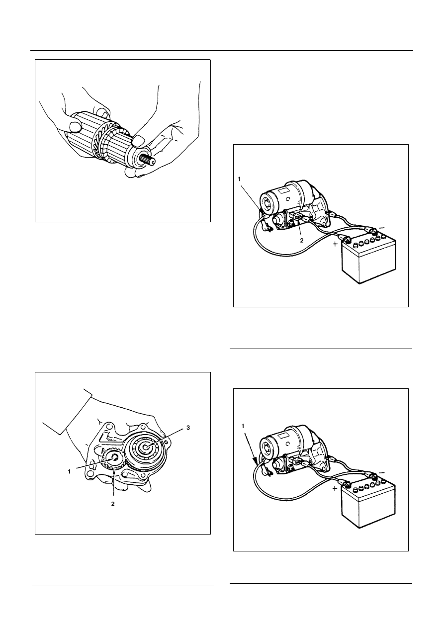
Magnetic Switch
Temporarily connect the solenoid switch between the
clutch and the housing and run the following tests.
Complete each test within three to five seconds.
1. Pull-in test
Connect the battery negative terminal with the so-
lenoid switch body and the M terminal. When cur-
rent is applied to the 50 terminal from the battery
positive terminal, the pinion should flutter.
2. Hold-in test
Disconnect the lead at the M terminal. The pinion
should continue to flutter.
Legend
1. Roller
2. Idle gear
3. Steel ball
N6A3514E
N6A3515E
Legend
1. M terminal
2. 50 terminal
Legend
1. Disconnect
N6A3516E
N6A3517E