Isuzu N-Series. Manual - part 582


  Index      Isuzu     Isuzu N-Series - service repair manual


Search            


Content   ..  580  581  582  583   ..


Isuzu N-Series. Manual - part 582


6A1-16 4JB1/4JB1-TC/4JG2/4JH1-TC - ENGINE

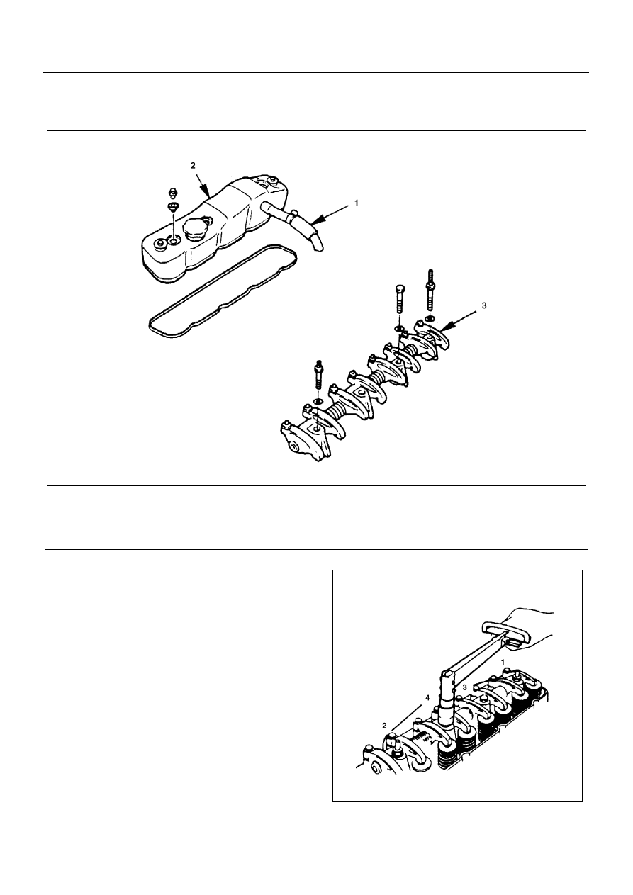
ROCKER ARM SHAFT ASSEMBLY

Component

Removal

Preparation

• Disconnect battery ground cable.

1. PCV Hose
2. Cylinder Head Cover
3. Rocker Arm Shaft Assembly

• Loosen bolts and nuts of rocker shaft bracket by

turns and remove rocker shaft assembly.

Legend

1. PCV hose

3. Rocker arm shaft assembly

2. Cylinder head cover

N6A3245E

N6A3246E

4JB1/4JB1-TC/4JG2/4JH1-TC - ENGINE 6A1-17

Installation

1. Rocker Arm Shaft Assembly

• Install rocker arm shaft with larger oil hole 

φ4) to

the front of engine.

• Align fixing bolt with nut of rocker arm shaft and

tighten fixing bolts to the specified torque.

Tighten:

• 54 N

⋅m (5.5 kg⋅m / 40 lb⋅ft)

2. Valve clearance adjustment

1) Bring the piston in either the No.1 cylinder or

the No.4 cylinder to TDC on the compression
stroke by turning the crankshaft until the crank-
shaft damper pulley TDC line is aligned with the
timing pointer.

2) Check the rocker arm shaft bracket nuts for

looseness.
Tighten any loose rocker arm shaft bracket
nuts before adjusting the valve clearance.

Tighten:

• Rocker arm shaft bracket nut to 54 N

⋅m (5.5 kg⋅m / 40

lb

⋅ft)

3) Check for play in the No.1 intake and exhaust

valve push rods.
If the No.1 cylinder intake and exhaust valve
push rods have play, the No.1 piston is at TDC
on the compression stroke.
If the No.1 cylinder intake and exhaust valve
push rods are depressed, the No.4 piston is at
TDC on the compression stroke.

Adjust the No.1 or the No.4 cylinder valve clear-
ances while their respective cylinders are at
TDC on the compression stroke.

4) Loosen each valve clearance adjusting screw

as shown in the illustration.

N6A3119E

N6A3026E

Valve Clearance (At Cold)

mm (in)

0.4 (0.016)

N6A3091E

N6A3028E

6A1-18 4JB1/4JB1-TC/4JG2/4JH1-TC - ENGINE

No. 1 Cylinder T.D.C (Compression stroke)

5) Insert a feeler gauge of the appropriate thick-

ness between the rocker arm and the valve
stem end.

6) Turn the valve clearance adjusting screw until

a slight drag can be felt on the feeler gauge.

7) Tighten the lock nut securely.
8) Rotate the crankshaft 360

°.

9) Realign the crankshaft damper pulley TDC

notched line with the timing pointer.

10) Adjust the clearances for the remaining valves

as shown in the illustration.

No. 4 Cylinder T.D.C (Compression stroke)

3. Cylinder Head Cover

• Install cylinder head cover and tighten bolts to the

specified torque.

Tighten:

• 13 N

⋅m (1.3 kg⋅m / 113 lb⋅in)

4. PCV Hose

• Connect battery ground cable.

N6A3249E

N6A3250E

4JB1/4JB1-TC/4JG2/4JH1-TC - ENGINE 6A1-19

VALVESTEM OIL CONTROLLER & VALVE SPRING

Component

Removal

Preparation

• Disconnect battery cable.

1. Cylinder Head Cover
2. Rocker Arm Shaft Assembly

• Loosen bolts and nuts of rocker shaft bracket by

turns and removal rocker shaft assembly.

3. Valve Spring

• Apply compressed air to cylinder from the glow

plug hole hold the valve in place.

• Using special tool, compress valve spring and re-

moval split cover.
Valve spring compressor: 9-8523-1423-0 (J-
29760)

Legend

1. Cylinder head cover

3. Valve spring

2. Rocker arm shaft assembly

4. Valve guide oil seal

N6A3251E

N6A3075E


Content   ..  580  581  582  583   ..