Isuzu N-Series. Manual - part 579


  Index      Isuzu     Isuzu N-Series - service repair manual


Search            


Content   ..  577  578  579  580   ..


Isuzu N-Series. Manual - part 579


6A1-4 4JB1/4JB1-TC/4JG2/4JH1-TC - ENGINE
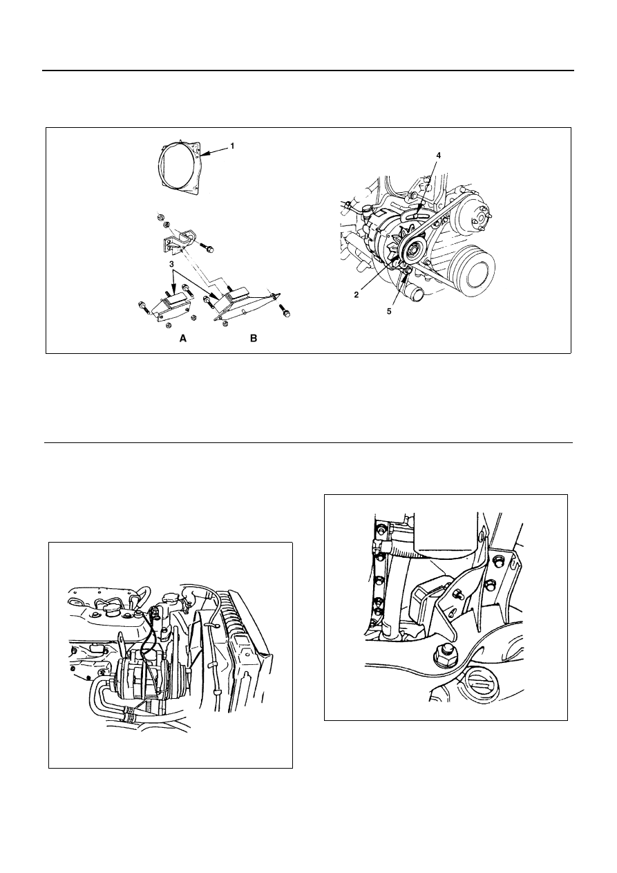
ENGINE MOUNT (RH)

Component

Removal

Preparation

• Disconnect battery ground cable.

1. Fan Shroud

• Remove reservoir tank hose and fan shroud.

2. Fan Belt

• Remove adjust plate lock bolt.
• Loosen generator fixing bolt then remove fan belt.

3. Support Rubber

• Remove two fixing nuts at the crossmember side.

• Separate the generator from the engine.
• Remove the support rubber nut from engine foot

side.

• Remove the support rubber while raising the en-

gine.

Legend

A. Rigid suspension

3. Support rubber

B. Independent suspension

4. Lock bolt

1. Fan shroud

5. AC generator fixing bolt

2. Fan belt

N6A3222E

N6A3223E

N6A3224E

4JB1/4JB1-TC/4JG2/4JH1-TC - ENGINE 6A1-5

Installation

1. Support Rubber

• Install the support rubber while raising the engine.
• Tighten the fixing nuts to the specified torque.

Tighten:

• Engine foot side to 82 N

⋅m (8.4 kg⋅m / 61 lb⋅ft)

• Crossmember side to 40 N

⋅m (4.1 kg⋅m / 30 lb⋅ft)

2. Fan Belt

• Install the fan belt.
• Depress the fan belt mid-portion with a 98 N (10 kg/

22 lb) force.

• Tighten the fixing bolt to the specified torque.

Tighten:

• Adjust plate lock bolt to 19 N

⋅m (1.9 kg⋅m / 14 lb⋅ft)

• Generator fixing bolt to 40 N

⋅m (4.1 kg⋅m / 30 lb⋅ft)

3. Fan Shroud

• Install the fan shroud and clip the reservoir tank

hose.

N6A3225E

N6A3226E

Legend

1. A/C compressor drive belt
2. P/S oil pump drive belt

6A1-6 4JB1/4JB1-TC/4JG2/4JH1-TC - ENGINE

ENGINE MOUNT (LH)

Component

Removal

Preparation

• Disconnect battery ground cable.

1. Air Intake Duct

• Remove the intake duct.

2. Fan Shroud

• Remove reservoir tank hose and fan shroud.

3. Support Rubber

• Remove two fixing bolts at the crossmember side.

• Remove the support rubber nut from engine foot

side.

• Remove the support rubber while raising the en-

gine.

Legend

A. Rigid suspension

2. Fan shroud

B. Independent suspension

3. Support rubber

1. Air intake duct

N6A3227E

N6A3223E

N6A3228E

4JB1/4JB1-TC/4JG2/4JH1-TC - ENGINE 6A1-7

Installation

1. Support Rubber

• Install the support rubber while raising the engine.
• Tighten the fixing nuts to the specified torque.

Tighten:

• Engine foot side to 82 N

⋅m (8.4 kg⋅m / 61 lb⋅ft)

• Crossmember side to 40 N

⋅m (4.1 kg⋅m / 30 lb⋅ft)

2. Fan shroud

• Install the fan shroud and clip the reservoir tank

hose.

3. Air Intake Duct

• Install the air intake duct.
• Connect battery ground cable.

N6A3229E

N6A3228E

N6A3223E


Content   ..  577  578  579  580   ..