Isuzu N-Series. Manual - part 555


  Index      Isuzu     Isuzu N-Series - service repair manual


Search            


Content   ..  553  554  555  556   ..


Isuzu N-Series. Manual - part 555


SERVICE INFORMATION 00-35

1. Find a safe place to park the vehicle.
2. Open the engine hood and place a container (Ap-

proximately 0.2 liter capacity) at the end of the vinyl
hose beneath the drain plug on the separator.

3. Loosen the drain plug by turning it counterclock-

wise (Approximately 5 turns) and operate the prim-
ing pump up and down about 10 times until water
is drained approximately 0.1 liter.

4. After draining, securely tighten the drain plug by

turning it clockwise and operate the priming pump
manually up and down several times.

5. After starting the engine, check to see that there is

no fuel leak from the drain plug. Also check to see
that the fuel filter water indicator light has turned
off.
If water separator requires frequent draining, have
the fuel tank drained for removal of water at your
Isuzu Dealer.

Air Bleeding

1. Loosen the bleeding plug on the injection pump

overflow valve.

2. Operate the priming pump until fuel mixed with

foam flows from the bleeding plug.

3. Tighten the bleeding plug.
4. Operate the priming pump several times and check

for fuel leakage.

Injection Pump Air Bleeding (4JH1-TC only)

Injection pump air bleeding is required to start the en-
gine when —

• The fuel supply has been exhausted (running out

of gas).

• The fuel filter has been replaced.
• The injection pump has been replaced.

Caution:
If the injection pump has been replaced, the air bleeding
procedure will require more time and effort (this is be-
cause there is no fuel in the pump).

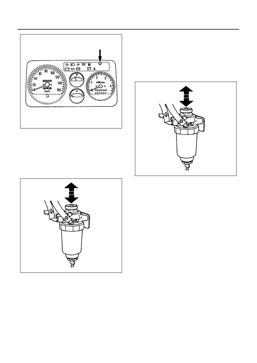
1. Loosen the air bleed nut on the priming pump

plunger (at the top of the fuel filter).

2. Move the priming pump plunger up-and-down until

strong resistance is felt (about 15 cycles).

3. Stop pumping and tighten the air bleed nut.
4. Wait for 1 minute.
5. Loosen the air bleed nut on the priming pump

plunger again.

6. Move the priming pump plunger up-and-down until

strong resistance if felt (about 10 cycles).

7. Stop pumping and tighten the air bleed nut.
8. Wait for 1 minute.
9. Loosen the air bleed nut on the priming pump

plunger again.

10. Move the priming pump plunger up-and-down until

strong resistance is felt (about 5 cycles).

11. Stop pumping and tighten the air bleed nut.

N6A3013E

N6A3012E

N6A3012E

00-36 SERVICE INFORMATION

12. Press the accelerator and clutch pedals all the way

to the floor and hold them down. Turn the ignition
switch to the ON position. Wait until the glow indi-
cator lamp turns on and off.

Caution:
If the engine is cold, the glow indicator light will stay on
for 4 — 7 seconds before turning off.
However, if the engine is hot, the lamp will not turn on.
13. Turn the ignition switch to the START position and

crank the engine until it starts (do not crank the en-
gine for more than 10 seconds).
If the engine does not start, repeat Steps 9 — 13.

14. Allow the engine to idle for 5 minutes.

Cooling System

Coolant Level

Check the coolant level and replenish the radiator re-
serve tank as necessary.
If the coolant level falls below the “MIN” line, carefully
check the cooling system for leakage. Then add enough
coolant to bring the level up to the “MAX” line.

Engine Coolant Change Procedure

1. To change engine coolant, make sure that the en-

gine is cool.

Warning:

WARNING:
WHEN THE COOLANT IS HEATED TO A HIGH TEM-
PERATURE, BE SURE NOT TO LOOSEN OR RE-
MOVE THE RADIATOR CAP. OTHERWISE YOU
MIGHT GET SCALDED BY HOT VAPOR OR BOILING
WATER. TO OPEN THE RADIATOR CAP, PUT A
PIECE OF THICK CLOTH ON THE CAP AND LOOS-
EN THE CAP SLOWLY TO REDUCE THE PRESSURE
WHEN THE COOLANT HAS BECOME COOLER.

2. Open radiator cap and drain the cooling system by

loosening the drain valve on the radiator and on the
cylinder body.

Notice:
For best result it is suggested that the engine cooling
system be flushed at least once a year. It is advisable to
flush the interior of the cooling system including the ra-
diator before using anti-freeze (ethylene-glycol based).
Replace damaged rubber hoses as the engine anti-
freeze coolant is liable to leak out even minor cracks.
Isuzu recommends to use Isuzu genuine anti-freeze
(ethylene-glycol based) or equivalent, for the cooling
system and not add any inhibitors or additives.

Caution:
A failure to correctly fill the engine cooling system in
changing or topping up coolant may sometimes cause
the coolant to overflow from the filler neck even before
the engine and radiator are completely full. If the engine
runs under this condition, shortage of coolant may pos-
sibly result in engine overheating. To avoid such trouble,
the following precautions should be taken in filling the
system.

3. To refill engine coolant, pour coolant up to filler

neck using a filling hose which is smaller in outside
diameter of the filler neck.
Otherwise air between the filler neck and the filling
hose will block entry, preventing the system from
completely filling up.

4. Keep a filling rate of 9 liter/min. or less. Filling over

this maximum rate may force air inside the engine
and radiator. And also, the coolant overflow will in-
crease, making it difficult to determine, whether or
not the system is completely full.

5. After filling the system to the full, pull out the filling

hose and check to see if air trapped in the system
is dislodged and the coolant level goes down.
Should the coolant level go down, repeat topping-
up until there is no more drop in the coolant level.

Legend

1. Reserve tank

N6A3390E

N6A3015E

SERVICE INFORMATION 00-37

6. After directly filling the radiator, fill the reservoir to

the maximum level.

7. Install and tighten radiator cap and start the en-

gine. After idling for 2 to 3 minutes, stop the engine
and reopen radiator cap. If the water level is lower,
replenish.

Warning:

WARNING:
WHEN THE COOLANT IS HEATED TO A HIGH TEM-
PERATURE, BE SURE NOT TO LOOSEN OR RE-
MOVE THE RADIATOR CAP. OTHERWISE YOU
MIGHT GET SCALDED BY HOT VAPOR OR BOILING
WATER. TO OPEN THE RADIATOR CAP, PUT A
PIECE OF THICK CLOTH ON THE CAP AND LOOS-
EN THE CAP SLOWLY TO REDUCE THE PRESSURE
WHEN THE COOLANT HAS BECOME COOLER.

8. After tightening radiator cap, warm up the engine at

about 2,000 rpm. Set heater adjustment to the
highest temperature position, and let the coolant
circulate also into heater water system.

9. Check to see the thermostat has opened through

the needle position of water thermometer, conduct
a 5 minutes idling again and stop the engine.

10. When the engine has been cooled, check filler

neck for water level and replenish if required.
Should extreme shortage of coolant is found,
Check the coolant system and reservoir tank hose
for leakage.

11. Fill the coolant into the reservoir tank up to “MAX”

line.

Cooling System Inspection

Install a radiator filler cap tester to the radiator. Apply
testing pressure to the cooling system to check for leak-
age.
The testing pressure must not exceed the specified
pressure.

Radiator Cap Inspection

The radiator filler cap is designed to maintain coolant
pressure in the cooling system at 1.05 kg/cm

2

 (15 psi /

103 kPa). Check the radiator filler cap with a radiator fill-
er cap tester. The radiator filler cap must be replaced if
it fails to hold the specified pressure during the test pro-
cedure.
Radiator Filler Cap Pressure

Thermostat Operating Test

1. Completely submerge the thermostat in water.
2. Heat the water.

Stir the water constantly by suitable wood bar (1) to
avoid direct heat being applied use wood plate (2)
to the thermostat.

3. Check the thermostat initial opening temperature.

4. Check the thermostat full opening temperature.

Testing Pressure

kPa (Kg/cm

2

/psi)

147 (1.5/21)

N6A3016E

Pressure Valve

kPa (kg/cm

2

/psi)

88 — 118 (0.9 — 1.2/12.8 — 17.1)

Negative Valve (Reference)

kPa (kg/cm

2

/psi)

1.0 — 13.9 (0.01 — 0.04/0.14 — 0.57)

Thermostat Initial Opening 
Temperature

°C (°F)

82 (180)

Thermostat Full Opening 
Temperature

°C (°F)

95 (203)

Valve Lift at Fully Open 
Position

mm (in)

10 (0.39)

N6A3017E

00-38 SERVICE INFORMATION

Drive Belt Adjustment

Depress the drive belt mid portion with a 98 N (10 kg /
22 lb) force.

Check the drive belt for cracking and other damage.

1. Crankshaft damper pulley (1)
2. Generator pulley (2)
3. Cooling fan pulley (3)
4. Oil pump pulley or idler pulley (4)
5. Compressor pulley or idle pulley (5)

Cooling Fan Pulley Drive Belt 

Fan belt tension is adjusted by moving the generator.
Depress the drive belt mid portion with a 98 N (10 kg /
22 lb) force.

1. Crankshaft damper pulley (1)
2. Generator pulley (2)

3. Cooling fan pulley (3)

Compressor Pulley Drive Belt

Move the idler pulley as required to adjust the compres-
sor drive belt tension.
If the vehicle is equipped with power steering, move the
oil pump as required.
Depress the drive belt mid portion with a 98 N (10 kg /
22 lb) force.

1. Crankshaft damper pulley (1)
2. Oil pump pulley or idler pulley (2)

Power Steering Oil Pump Pulley Drive Belt

Move the oil pump as required to adjust the oil pump
drive belt tension.
On air conditioner equipped models, both drive belts
pulley must always be replaced as a set.

Drive Belt Deflection

mm (in)

8 — 12 (0.32 — 0.47)

N6A3018E

N6A3019E

Belt Deflection

mm (in)

8 — 12 (0.32 — 0.47)

N6A3020E

N6A3021E


Content   ..  553  554  555  556   ..