Isuzu N-Series. Manual - part 488


  Index      Isuzu     Isuzu N-Series - service repair manual


Search            


Content   ..  486  487  488  489   ..


Isuzu N-Series. Manual - part 488


Engine Mechanical (4HK1-TC)   6A-57

9. Check if the rocker arm shaft is worn.

• Use a micrometer to measure 8 places rubbed

by the rocker arms.

• Replace the shaft if the diameter is less than

the limit.

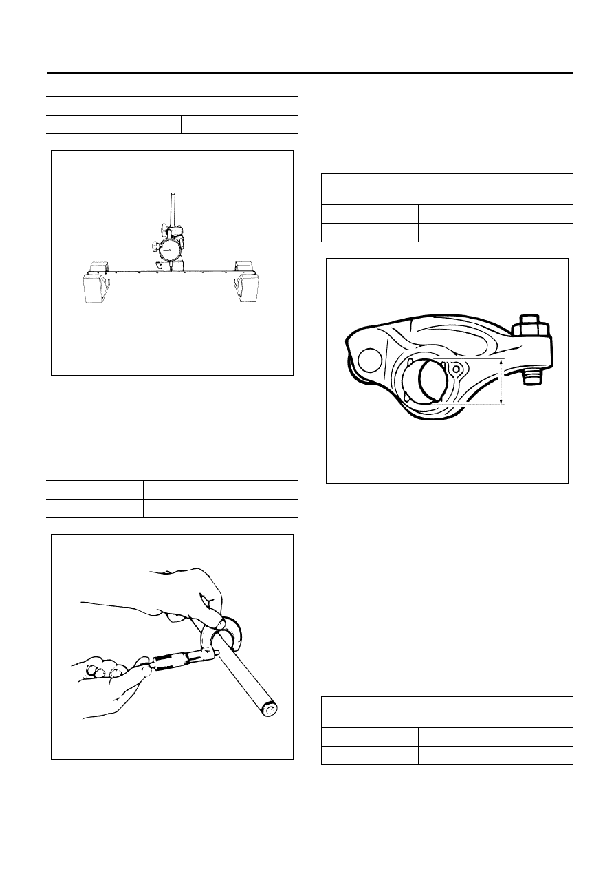
10. Inspect a clearance between the rocker arm and

the rocker arm shaft.

• Use a cylinder gauge to measure an inside

diameter of the bush of the rocker arm to
measure a clearance between the external
diameter of the shaft.

• If the measurement exceeds the limit, replace

the rocker arm and the shaft.

11. Inspect a clearance between the roller of the

rocker arm and the rocker arm pin.
a. Pass a string, through the opening between the

rocker arm and the roller, pull it strongly in the
direction indicated with arrows and measure
the gap between the rocker arm and the roller
with the roller being hulled out. (Figure 1) 

b. After marking the measuring point, pull the

string out push the roller fully into the rocker
arm, and measure the gap of the marked place.
(Figure 2) 

c. The gap between the measurement taken

under a. and that under b. Is the a clearance
between the roller and the rocker arm pin. If it
exceeds the limit, replace the rocker arm.

Bend of the rocker arm shaft

mm (in)

Limit

0.3 (0.012)

External diameter of the rocker arm shaft

mm (in)

Standard

21.979 – 22.000 (0.865 – 0.866)

Limit

21.85 (0.860)

N6A6087E

N6A6088E

Clearance between the rocker arm and 
rocker arm shaft

mm (in)

Standard

0.010 – 0.056 (0.0004 – 0.0022)

Limit

0.2 (0.0079 )

Clearance between the roller and the 
rocker arm pin

mm (in)

Standard

0.068 – 0.100 (0.0026 – 0.0039)

Limit

0.2 (0.0079)

N6A6089E

6A-58   Engine Mechanical (4HK1-TC)

Reassembly

1. Install the camshaft bracket to one side of the

rocker arm shaft tentatively first. (Tighten them up,
after the rocker arm shaft assembly is installed on
the cylinder head.)

• Assemble in the reverse order to dismounting.

2. Install the rocker arm.

• Apply engine oil to the hole of the rocker arm,

the roller and the rocker arm pin.

3. Install the wave washer between the rocker arm.
4. Install the rocker arm bracket.

• Paying attention to the direction of the rocker

arm bracket, repeat the step 2 to 4.

5. Install the camshaft bracket.

• Install the camshaft bracket on the rocker arm

shaft with the bolts indicated with an arrow
tightened tentatively. (Tighten them up, after the
rocker arm shaft assembly is installed on the
cylinder head.)

Legend

1. Camshaft Bracket
2. Rocker Arm
3. Wave Washer
4. Rocker Arm
5. Rocker Arm Bracket
6. Camshaft Bracket
7. Rocker Arm Shaft


N6A6090E

N6A6091E

N6A6092E

N6A6085E

Engine Mechanical (4HK1-TC)   6A-59

Installation

1. Install the rocker arm shaft assembly.

• If the bridge cap comes off, apply engine oil

over the inside of the bridge cap and put it
together with the bridge.

Caution:
Pay full attention so as not to drop the bridge cap in the
gear case of the rear part of the cylinder head or the
hole into which oil pours back in the front.

Legend

1. Bridge Cap
2. Bridge


1) Temporarily tighten the bolts marked with the

arrow in the illustration.

2) Loosen the rocker arm adjust screws and apply

engine oil to the rocker arm roller portions.

3) Install the rocker arm assembly on the cylinder

head.

• Apply engine oil on threads of the bolts and

nuts, and fix them tentatively (about tighten up).

• Tighten them up according to the order

specified below gradually, taking care not to
incline the entire rocker arm assembly.
Tightening order:
1. Nuts (1) from near side of the rocker arm
shaft
2. Bolts (2)
3. Bolts (3) from out side
4. Bolts (4)

Tighten:
Bolt (3) to 56 N

⋅m (5.7 kg⋅m/41 lb ft)

Nut (1), Bolt (2), (4) to 27 N

⋅m (2.8 kg⋅m/20 lb ft)

Legend

1. Camshaft Bracket Fixing Nut
2. Camshaft Bracket Fixing Bolt
3. Rocker Arm Bracket Fixing Bolt
4. Rocker Arm Shaft Set Bolt


• Adjust valve clearance.

Refer to “Functional Inspection”.

2. Install the cylinder head cover.

Refer to “Cylinder Head Cover”.

N6A6093E

N6A6084E

N6A6094E

6A-60   Engine Mechanical (4HK1-TC)

Torque Specifications

N6A6095E


Content   ..  486  487  488  489   ..