Isuzu N-Series. Manual - part 460


  Index      Isuzu     Isuzu N-Series - service repair manual


Search            


Content   ..  458  459  460  461   ..


Isuzu N-Series. Manual - part 460


6E-176 EMISSION AND ELECTRICAL DIAGNOSIS

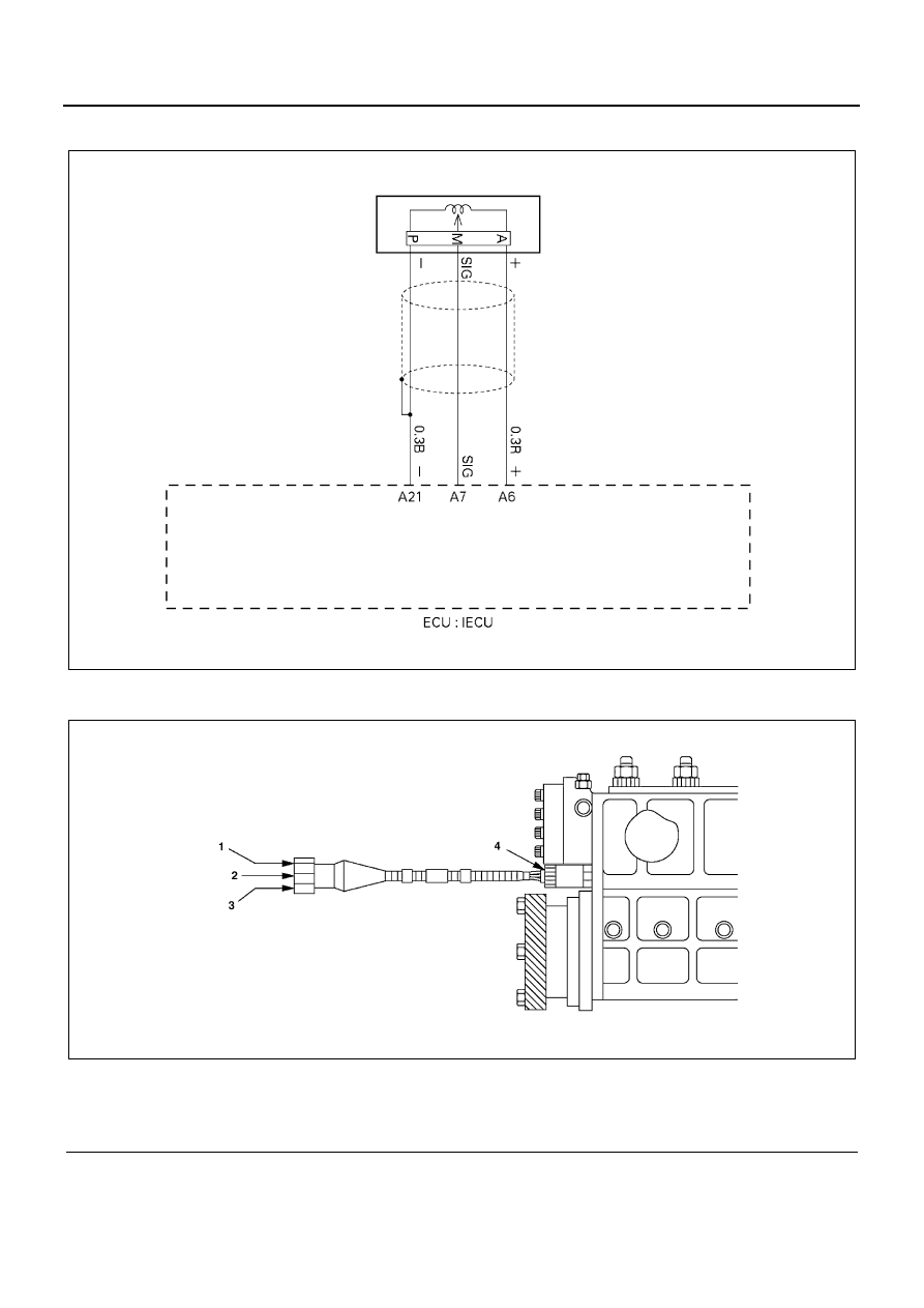
DTC-22 Rack Sensor Circuit High Voltage

Location of Rack Sensor Connector

Legend

1. OSC (red)

3. GND (black)

2. MDL (white)

4. Rack sensor

N6A1319E

N6A1320E

EMISSION AND ELECTRICAL DIAGNOSIS 6E-177

Connector Name of Rack Sensor

Notice:
Mark “___” on connector which is plugged, therefore,
should be confirmed to be played.

Relation Between Connector Number and Signal
Name

Connector 

No

Signal name

Wire color

1

Rack sensor (OSC)

R

2

Rack sensor (GND)

B

4

Rack sensor (MDL)

W

N6A1321E

6E-178 EMISSION AND ELECTRICAL DIAGNOSIS

Step

Action

Value

YES

NO

1

Was the “Diagnostic system check” per-
formed?

Go to Step 2

Go to diagnostic 

system check

2

Remove Sensor Connector.

Has DTC22 been corrected? (Ignore DTC 21)

Go to Step 3

Go to Step 7

3

1. Jumper Harness signal Terminal and

GND terminal at the Sensor side of Con-
nector.

2. Ignition “ON”

Has DTC22 been corrected?

Go to Step 4

Go to Step 5

4

1. Check the Sensor Connector for inter ter-

minal short.
After check, repair if necessary.

Was Connector Terminal shorted?

Go to Step 12

Go to Step 6

5

1. Check the GND Circuit for disconnect.

After check, repair if necessary.

Is GND circuit disconnect?

Go to Step 12

Go to Step 11

6

1. Check the Sensor Harness signal circuit

and power source circuit for short.
After check, repair if necessary.

Was Harness shorted?

Go to Step 12

Go to Step 8

7

1. Check the Harness signal circuit and pow-

er source for short.
After check, repair if necessary.

Was Harness shorted?

Go to Step 12

Go to Step 11

8

1. Apply 5V to RACK+ TERMINAL.
2. Measure RACK SIG Voltage.

Is RACK SIG VOLTAGE as specified?

0.9 — 2.0V

(Idling speed)

Go to Step 9

Go to Step 10

9

1. Check the iron core of RACK Sensor for

damage, seizure, and wear.

2. After check, repair if necessary.

Was there any trouble in the iron core(RACK
end) inside RACK Sensor?

Go to Step 12

Go to Step 11

10

Replace the RACK Sensor.

Is the action complete?

Go to Step 12

11

Replace the ECM.

Is the action complete?

Go to Step 12

12

1. Reconnect all the connectors removed.
2. Ignition “ON”, Engine “OFF”

Is DTC22 all right under Scan Tool Check?

Go to Step 13

Go to Step 2

13

Is any current trouble other than DTC 22 dis-
played by indicator light?

Go to trouble code 

section

Trouble code clear

EMISSION AND ELECTRICAL DIAGNOSIS 6E-179

DTC-31 Exhaust Gas Recirculation (EGR) Vacuum Switching Valve (VSV) Solenoid Control
Low Voltage

N6A1325E


Content   ..  458  459  460  461   ..