Isuzu N-Series. Manual - part 449


  Index      Isuzu     Isuzu N-Series - service repair manual


Search            


Content   ..  447  448  449  450   ..


Isuzu N-Series. Manual - part 449


6E-132 EMISSION AND ELECTRICAL DIAGNOSIS

Working Check

Apply powervoltage between the terminals, there
is no problem if the negative pressure does not rise
when applied to the input port.

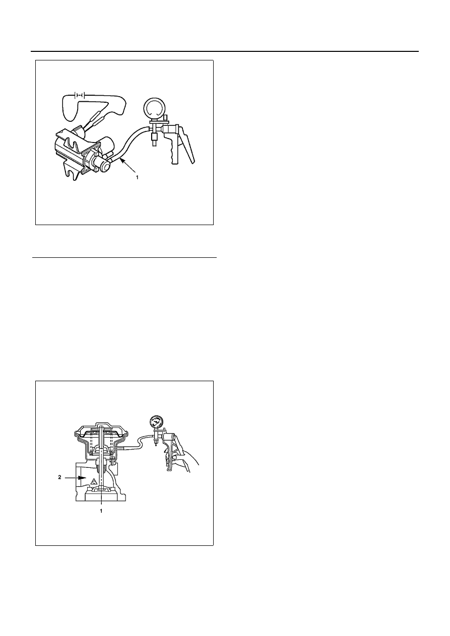
3. Exhaust Gas Recirculation (EGR) Valve (Equipped

with EGR and Variable Swirl System (VSS))
With negative pressure applied to the diaphragm
chamber, make sure that the valve is smoothly ac-
tuated to make the area between (1) and (2) venti-
lated. 
Startup: About -13.3 

± 2.7 kPa (-100 ± 20 mmHg /

-1.93 

± 0.39 psi)

Check to see if EGR valve is normally actuated un-
der the following conditions: 
QWS off (After warming up) 
Engine coolant temp.: 80

°C (176°F) or higher

Legend

1. Vacuum port

N6A1258E

N6A1259E

EMISSION AND ELECTRICAL DIAGNOSIS 6E-133

Variable Swirl System (VSS) System Malfunction (Equipped with Exhaust gas recirculation
and VSS)

N6A1675E

6E-134 EMISSION AND ELECTRICAL DIAGNOSIS

VSS (Variable Swirl System)

The Variable Swirl System (VSS) is designed to adjust the intensity of swirl by allowing or not allowing air to flow
through a sub-port (or bypass) the runs in parallel with the intake port for each cylinder. The swirl intensifies when
there is no air flow through the sub-port, and vice versa. 
The air flow is controlled by the on-off valve at the inlet to the sub-port and the valve in turn is turned on and off by
computer signals which are dependent on engine speed, load and coolant temperature, Basically, the air is cut off at
low speeds to maintain high swirl and is allowed to flow at high speeds to maintain low swirl.

Variable Swirl System (Equipped with Exhaust gas recirculation (EGR) and VSS)

Legend

1. Cylinder head

7. Vacuum

2. VSS case

8. VSV; VSS

3. Inlet port

9. Actuator

4. Sub-port

10. Thermo sensor

5. Control valve

11. Engine speed sensor

6. Inlet manifold

12. Rack sensor

N6A1261E

EMISSION AND ELECTRICAL DIAGNOSIS 6E-135

Inspection

1. Thermosensor (Engine coolant temperature)

Soak the temperature sensitive part of a ther-
mosensor in the water, and while changing the wa-
ter temperature, make sure the resistance is
changed as the following graph shows:

2. Vacuum Switching Valve (VSV)

Resistance Check

Check the resistance between the VSV connector
terminals using a circuit tester.
Cold Resistance
: 37 — 44 (

Ω) (for 12 volt)

: 159 — 169 (

Ω) (for 24 volt)

Connect battery voltage between VSV connector
terminals and make sure of the continuity between
the ports.

Airtight Check

Apply negative pressure to the negative pressure
input port as illustrated on the left. 
Although there is leakage, it is no problem if the
negative pressure rises to -46.7 kPa (-350 mmHg /
-6.77 psi) or more.

Legend

1. Resistance (k

Ω)

2. ECT 

°F (°C)

N6A1254E

N6A1255E

Legend

1. 2 Pin
2. Port

N6A1264E

N6A1265E


Content   ..  447  448  449  450   ..