Isuzu N-Series. Manual - part 443


  Index      Isuzu     Isuzu N-Series - service repair manual


Search            


Content   ..  441  442  443  444   ..


Isuzu N-Series. Manual - part 443


6E-108 EMISSION AND ELECTRICAL DIAGNOSIS

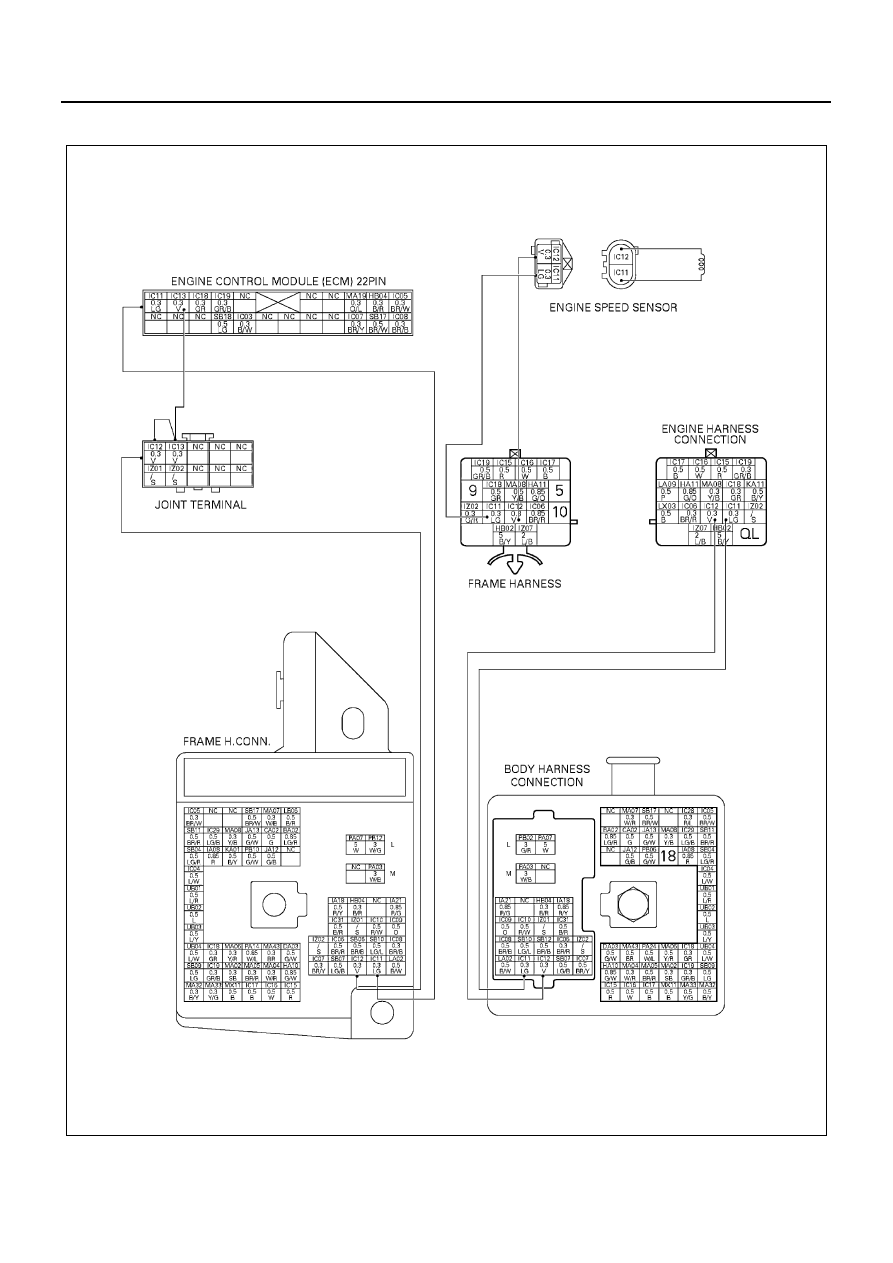
DTC-P45 Engine Speed Sensor Circuit Low Voltage

N6A1228E

EMISSION AND ELECTRICAL DIAGNOSIS 6E-109

Appearance of Engine Speed Sensor and Con-
nector Name

Engine Speed Sensor

Engine Speed Sensor Connector

Measure Resistance at Engine Speed Sensor

Caution:
When measuring resistance with a circuit tester, be careful not to damage or deform the terminals.

Legend

1. To engine speed sensor
2. 2 pin

N6A1229E

Legend

1. To engine speed sensor
2. 2 pin

Connector No

Signal

1

GND

2

SIG

N6A1230E

Legend

1. Circuit tester

3. Engine speed sensor

2. Remove engine wire harness

4. Measure resistance between connector pin

N6A1231E

6E-110 EMISSION AND ELECTRICAL DIAGNOSIS

Resistance value

Notice:
Resistance value is difference according to the engine temperature (condition of engine warming up).

Location of Fuse

Inspection Point

Resistance Value

(k

Ω)

Reference

Connector

Pin No.

2 pin Black

←→ 1

840

±20%

SIG 

←→ GND

←→ Body

SIG 

←→ Body

Legend

1. Fuse puller

3. Label

2. Spare fuses

4. Fuses (F-1 — F-24)

N6A1232E

EMISSION AND ELECTRICAL DIAGNOSIS 6E-111

Step

Action

Value

YES

NO

1

1. Ignition “ON”, Engine “OFF”
2. Connect a voltmeter to the ECM connec-

tor terminals (ENGINE+) and (ENGINE-)

Is the voltage 0V?

Go to Step 3

Go to Step 5

2

1. Ignition “ON”, Engine “ON”
2. Connect a voltmeter to the ECM connec-

tor terminals (ENGINE+) and (ENGINE-).

Is the voltage under the range of 0 — 1V (AC
intermittently) when the engine speed is about
2000RPM? Does the Voltage increase as the
engine speed is increased?

Go to Step 4

Go to Step 6

3

Check for poor sensor ground or sensor signal
circuit terminal connection and terminal
shorted at the ECM and replace terminal(s) if
necessary.

Did any of the terminals need to be replaced?

Go to Step 8

Go to Step 4

4

1. Check sensor signal circuit for disconnec-

tion and power source for short.

2. Check sensor GND circuit for disconnec-

tion and power source for short.

3. Repair if necessary. 

Was repair needed?

Go to Step 8

Go to Step 5

5

1. Check signal circuit for GND short.
2. Repair if necessary.

Was repair needed?

Go to Step 8

Go to Step 7

6

Replace the sensor.

Is the action complete?

Go to Step 8

7

Replace the ECM.

Is the action complete?

Go to Step 8

8

1. Reconnect all the connectors removed.
2. Ignition “ON”, Engine “OFF”
3. Connect the Scan Tool.
4. Ignition “ON” Engine “OFF”
5. Make Scan Tool indicate engine speed.

Is a speed range of 700 rpm to 900 rpm indi-
cated with the engine idling (accel. off)?

And as engine speed rises with accel. on,
does the indicated value rise?

Go to Step 9

Go to Step 2

9

Is any current trouble other than DTC 45 dis-
played by scan tool?

Go to trouble code 

section

Trouble code clear


Content   ..  441  442  443  444   ..