Isuzu N-Series. Manual - part 425
6E-36 EMISSION AND ELECTRICAL DIAGNOSIS
Governor (Model RLD-M)
The RLD-J type governor can be used with the MI,
MITICS injection pumps, and was designed to have bet-
ter control and endurance than the previous RLD type
governor.
Although the basic construction is identical to that of the
RLD type governor, the RLD-M type is larger to match
the applicable pumps’ larger size.
Features
Variable speed control governor with decreased le-
ver reaction force
As with the previous RLD type governor, RLD-M gover-
nor control is accomplished using the speed control le-
ver to change the fulcrum of the internal link mechanism.
Consequently, as the reaction force of the governor
spring does not act directly on the speed control lever,
only a very small lever reaction force is exerted on the
accelerator pedal.
Set torque characteristics through internal torque
cam
At full load, the tip of the sensor lever traces the face of
the torque cam to determine the full load rack position
and control the full load injection quantity.
Consequently, the torque characteristics demanded by
the engine can be freely set by changing the shape of
the torque cam face.
Improved control through internal guide plate
When the speed control lever is operated, the 2nd sup-
porting lever’s pin moves along the guide plate. The
floating lever connected to the pin thus moves to change
the ball joint fulcrum positions.
In the intermediate to high speed ranges, the guide plate
causes the floating lever to move to increase the lever
ratio continuously from 1.1 (idling) — 6 (full speed). This
increase in the lever ratio in the intermediate to high
speed range improves speed droop.
Legend
1. At maximum speed control
2. At idle speed control
3. Link mechanism
4. Speed control lever
5. Governor spring
N6A1147E
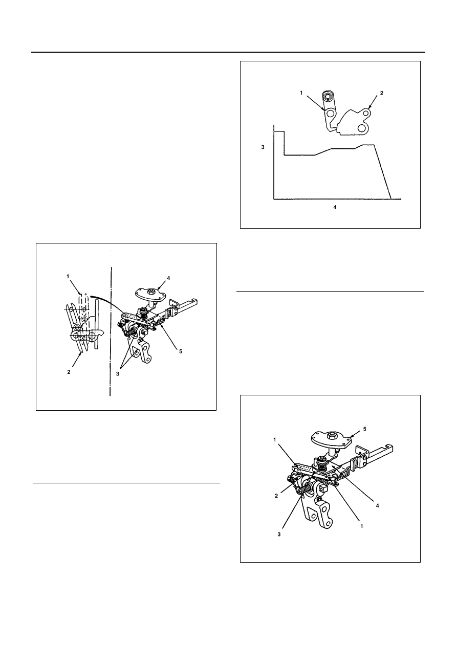
Legend
1. Sensor lever
2. Torque cam
3. Control rack position (mm)
4. Pump speed (r/min)
N6A1148E
N6A1149E