Isuzu N-Series. Manual - part 422


  Index      Isuzu     Isuzu N-Series - service repair manual


Search            


Content   ..  420  421  422  423   ..


Isuzu N-Series. Manual - part 422


6E-24 EMISSION AND ELECTRICAL DIAGNOSIS

How to read flashing of the indicator lamp:
The two-digit self-diagnosis code flashes starting from
ten’s figure to indicate the self-diagnosis code.
Please read the self-diagnosis code from the flashing.
If the plural self-diagnosis codes are indicated, the same
self-diagnosis code is flashed repeatedly in steps of
three times.
Please read it correctly.

• Diagnostic Trouble Code (DTC) outputting is done

in decreasingly order of DTC number.

• Indication is changed over on completion of output

DTC indication.

• DTC indicator is stopped with diagnostic switch be-

ing off.

• When there is no DTC output, “1” is outputted in

normal DTC code.

• After indicating 3 times pear 1 DTC, shift is con-

ducted to the next DTC. (After making a round, the
indications are repeated again.)

• In case of the same diagnostic code, it is used 1

DTC (3 times indication.)

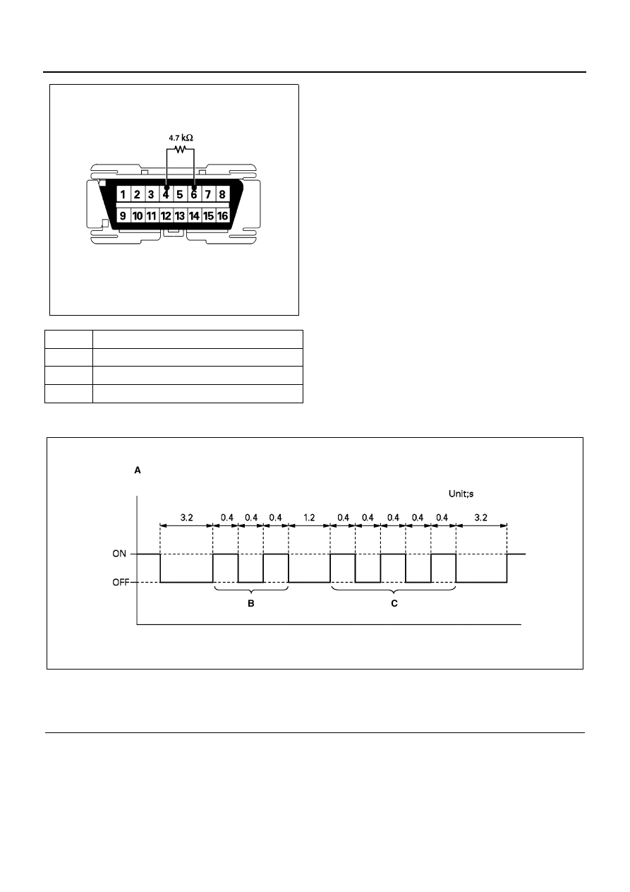
Example Diagnosis Trouble Code Output

NO

TERMINAL NAME

6

DIAG CONTROL

7

CHECKER SIG

4, 5

CHECKER GND

N6A1666E

Legend

A. (For example) In case of indicate two digits figure 

“DTC23”

B. Figure of ten

C. Figure of one

N6A1137E

EMISSION AND ELECTRICAL DIAGNOSIS 6E-25

Flashing of Indicator Lamp

Diagnosis Trouble Code List

* Equipped with EGR and VSS

Legend

A. Right-hand drive

C. Terminal assignment of data link connector (DLC)

B. Left-hand drive

DTC#

TECH 2 STRING

P21

Rack Sensor Circuit Low

P22

Rack Sensor Circuit High

P13

Engine Coolant Temperature (ECT) Sensor Circuit High

P14

ECT Sensor Circuit Low

P31 *

Exhaust Gas Recirculation (EGR) Electronic Vacuum Regulating Valve (EVRV) Solenoid Circuit Low

P32 *

EGR EVRV Solenoid Circuit High

P41

Quick On Start (QOS) Relay Control Circuit Low

P42

QOS Relay Control Circuit High

P23

Magnetic Switch Control Circuit Low

P24

Magnetic Switch Control Circuit High

P26

Quick Warm System (QWS) Relay Control Circuit High

P33 *

Variable Swirl System (VSS) Control Circuit Low

P34 *

VSS Control Circuit High

P43

Aneroid Compensator Vacuum Switching Valve (VSV) Control Circuit Low

P35 *

EGR Quick Cut VSV Control Circuit Low

P36 *

EGR Quick Cut VSV Control Circuit High

P44

Aneroid Compensator VSV Control Circuit High

P45

Engine Speed Sensor Circuit Low

P61

Barometric Sensor Circuit Error

P52

Electronically Erasable Programmable Read Only Memory (EEPROM) Error

N6A1667E

6E-26 EMISSION AND ELECTRICAL DIAGNOSIS

Error Classified

Trouble 

Code

Diagnostic Condition

Return 

Condition

Back Up

Judging 

Time

Relay:
QWS

+B short

P26

Output TR Monitor

When
forward
normal

QWS: R/L
Non-Continuity.

0.52 sec

VSV:
VSS

Harness Open 
GND short

*P33

Output TR Monitor

When
forward
normal

VSS: VSV
Output stop.

0.52 sec

+B short

*P34

VSV:
ANEC
ON

Harness Open 
GND short

P43

Output TR Monitor

When
forward
normal

ANECON: VSV
Output stop.

0.52 sec

+B short

P44

VSV:
EGR
Quick

Harness Open 
GND short

*P35

Output TR Monitor

When
forward
normal

EVRV: EGR
VSV: EGR Quick Cut
The above output stops.

0.52 sec

+B short

 *P36

Atmo-
spheric
Pres-
sure
Sensor

Output Abnor-
mal

P61

1.5V (49.9 kPa / 374
mmHg / 7.23 psi) or
lower, or 4.5V (160 kPa
/ 1200 mmHg / 23.2
psi) or higher detected.

When
forward
normal

EVRV: EGR
VSV: EGR Quick Cut
The above output stops.
ANECON: VSV is actu-
ated.

0.52 sec

ECM 
EEPROM 
error

P52

Check when ECM is
started and when Trou-
ble Code is written.

When
forward
normal

Trouble Code other than
52 (EEPROM error) not
indicated.

Normal

P12

No other trouble code.

No history of this diagno-
sis recorded

Rack
Sensor

Harness Open 
GND short

P21

Rack Voltage 0.3V or
lower, Engine speed
600 — 900rpm, and
water Temp. 0

°C

(32

°F) or higher are

detected for 3 seconds
running.

When
forward
normal

EVRV: EGR
VSV: EGR Quick Cut
VSV: VSS
The above outputs stop.
R/L: QWS Non-continuity
Idle position output stop.
The above outputs stop.
Rack Learning valve: 0

3.52 sec

+5V short
Rack Sensor 
Power Voltage

P22

5V or higher Rack Volt-
age detected.

0.52 sec

Water 
Temp 
Sensor

Harness Open
+B short

P13

-79

°C/-110°F (390kΩ)

or lower, or 120

°C/

248

°F (115kΩ) or

higher detected.

When 
forward 
normal

EVRV: EGR
VSV: EGR Quick Cut
VSV: VSS
MV: Timing Advance
The above outputs stop.
VSV: ANECON is actu-
ated
QOS: 0

°C or lower con-

trol

0.52 sec

GND short

P14

EVRV: 
EGR

Harness Open 
GND short

*P31

Output TR Monitor

When 
forward 
normal

EVRV: EGR
VSV: EGR Quick Cut
The above outputs stop.

1.57 sec

+B short

*P32

Relay 
QOS

Harness Open 
GND short

P41

Output TR Monitor

When 
forward 
normal

QOS: RL Non-continuity

0.52 sec

+B short

P42

EMISSION AND ELECTRICAL DIAGNOSIS 6E-27

* Equipped with EGR and VSS

Location of Sensor and Switch

Mag-
netic 
Vol-
ume 
Timing

Harness Open

P23

Output TR Monitor

When 
forward 
normal

Timing Advance: MV out-
put stop.

0.52 sec

GND short
+B short

P24

Harness Open 
GND short

P45

Engine speed 0, Rack
Voltage 

≥ 0.3V ≤ 0.57

is detected.

When 
forward 
normal

EVRV: EGR
VSV: EGR Quick Cut
VSV: VSS
R/L: QWS
The above outputs Idling 
position output stop 
when T/M POS SW out-
putted.
VSV: ANECON is actu-
ated

1.52 sec

Error Classified

Trouble 

Code

Diagnostic Condition

Return 

Condition

Back Up

Judging 

Time

N6A1139E


Content   ..  420  421  422  423   ..