Isuzu N-Series. Manual - part 389


  Index      Isuzu     Isuzu N-Series - service repair manual


Search            


Content   ..  387  388  389  390   ..


Isuzu N-Series. Manual - part 389


6C-34 FUEL SYSTEM

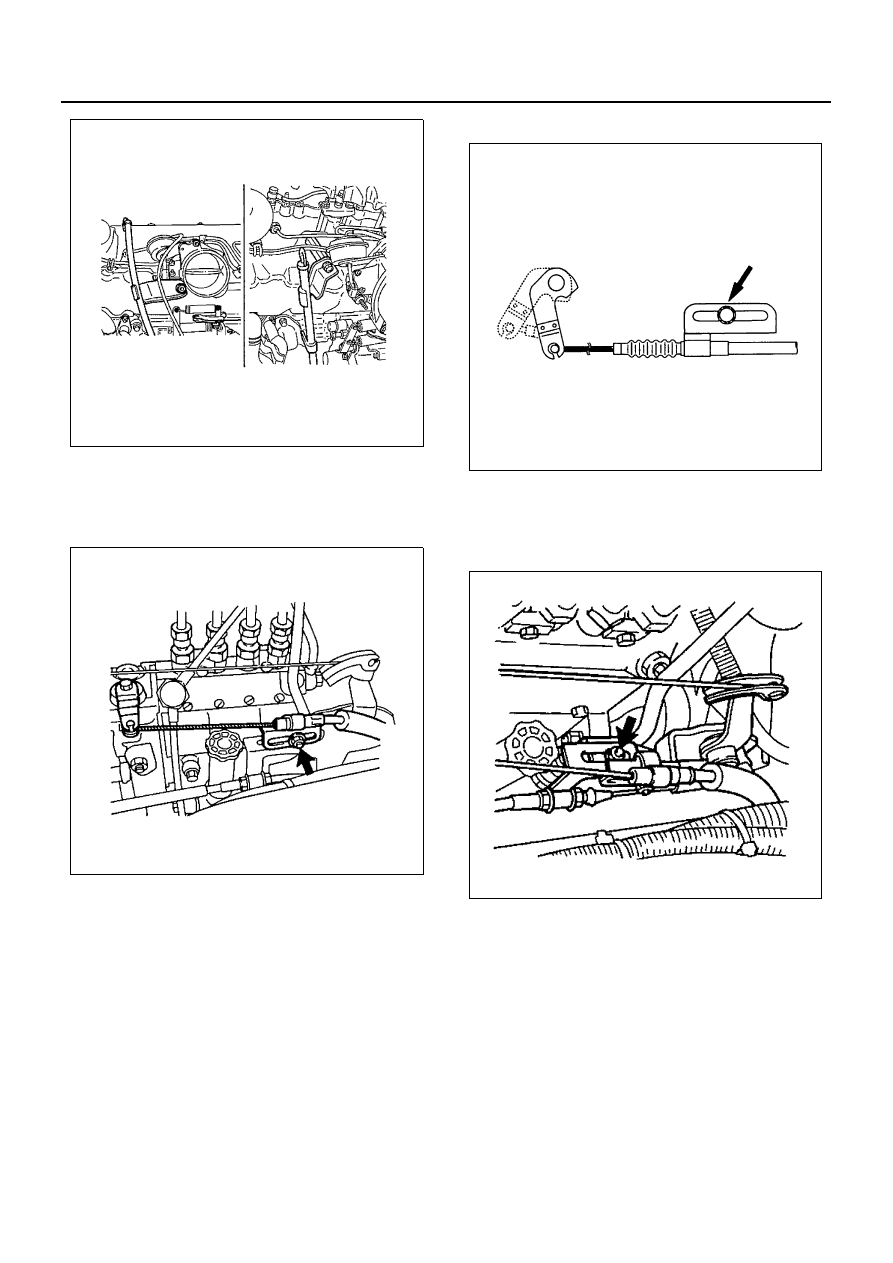
4. Engine Stop Cable

• Loosen the locking nut at bracket and discon-

nect engine stop cable from the injection pump
stop lever.

For 4HE1-TC

5. Accelerator Control Cable

• Loosen the locking nut at bracket and discon-

nect the accelerator control cable from the in-
jection pump control lever.

N6A0895E

N6A0930E

N6A0529E

N6A0898E

FUEL SYSTEM 6C-35

For 4HE1-TC

6. Engine Control Wire
7. Engine Control Lever
8. Oil Pipe
9. Fuel Return Hose

10. Fuel Feed Hose

• Disconnect fuel hose from injection pump side

and take care not to spill and enter dust.

11. Nozzle Cover

12. Leak-Off Pipe
13. Fuel Pipe
14. Fuel Filter Assembly
15. PCV Hose

16. Injection Pipe

• Loosen the injection pipe sleeve nuts (1).

Do not apply excessive force to the injection
pipes (5).

• Loosen the injection pipes clips (3).
• Remove the injection pipe assembly.

Plug the delivery valve holder (2) ports and
nozzle holder (4) ports with caps to prevent the
entry of foreign material.

17. Injection Pump Assembly

1) Remove the injection pump bracket bolts and

the injection pump rear bracket bolts.

2) Then remove the injection pump assembly.

N6A1653E

N6A0900E

N6A0901E

N6A0902E

6C-36 FUEL SYSTEM

18. Injection Pump Rubber Spacer (For 4HF1/4HG1)

Installation

1. Injection Pump Rubber Spacer

1) Stick the rubber spacer to the location indicated

in the illustration with pressure sensitive adhe-
sive double coated tape. (4HF1/4HG1 Engine)

2) 4HE1-TC (4HE1-XS) EURO-3 engines use a

larger rubber spacer than other engines. How-
ever, engines destined for Hong Kong do not
have a rubber spacer.

2. Injection Pump Assembly

1) Turn the crankshaft until the timing mark on the

crankshaft damper pulley is aligned with “13

°”

line.

2) Check the No.1 cylinder intake and exhaust

valve rocker arms for any play.
If the No.1 cylinder intake and exhaust valve
rocker arms are depressed the No.4 piston is at
on the compression stroke.
Rotate the crankshaft one full turn (360 de-
grees) and realign the crankshaft damper pul-
ley timing mark with the “13

°” line.

Notice:
BTDC 13

° to be aligned with here is an angle at which

the injection pump is installed, and has nothing to do
with the injection timing.

• Remove the inspection hole plug from the cyl-

inder body.

• Install the O-ring to the injection pump bracket.

N6A0903E

N6A0904E

N6A0904E

N6A0906E

FUEL SYSTEM 6C-37

3) Align the injection pump bracket slit with the

timer slit.

4) Install the injection pump assembly to the cylin-

der body.

Notice:
When the injection pump has a poor gear engagement
while installing the assembly to the cylinder body, insert
a screwdriver into the slit on the time peripheral with the
pump bracket slit used as a guide, and move it up and
down to get it into forcibly.

5) After installing the injection pump, the injection

timing can be checked through the timing
check hole provided at the injection pump
bracket.
Set the No.1 cylinder to the BTDC (injection
timing of engine mode) on the compression
stroke. When the pointer of the timing check
hole comes in line with the mark on the timer
periphery of the injection pump as shown in the
illustration, the injection timing is normal.
After completion of the injection timing check,
tighten the check hole plug to the specified
torque.

For 4HE1-TC

6) Turn the crankshaft until the timing mark on the

crankshaft damper pulley is aligned with “8

°”

(98EPA) or “9

°” (Spec EURO3) line.

Notice:
Position in its normal rotating direction. (for 4HE1-TC
only)

Legend

1. TDC

Injection Timing

deg

4HF1:

4HE1-TC (4HE1-XS, XN)

BTDC 8

4HG1

BTDC 9

4HG1-T

BTDC 7

BTDC 9 (For Colombia)

4HE1-TC (4HE1-XS)

BTDC 9 (Spec EURO3)

N6A0907E

Legend

1. Pointer
2. Timer outside mark
3. Timing check hole

Legend

1. 8

° mark

2. Pointer
3. 13

° mark

4. Timing check hole

N6A0908E

N6A0909E


Content   ..  387  388  389  390   ..