Isuzu N-Series. Manual - part 353


  Index      Isuzu     Isuzu N-Series - service repair manual


Search            


Content   ..  351  352  353  354   ..


Isuzu N-Series. Manual - part 353


6A3-64 ENGINE (4HF1 / 4HF1-2 / 4HE1-TC / 4HG1 / 4HG1-T)
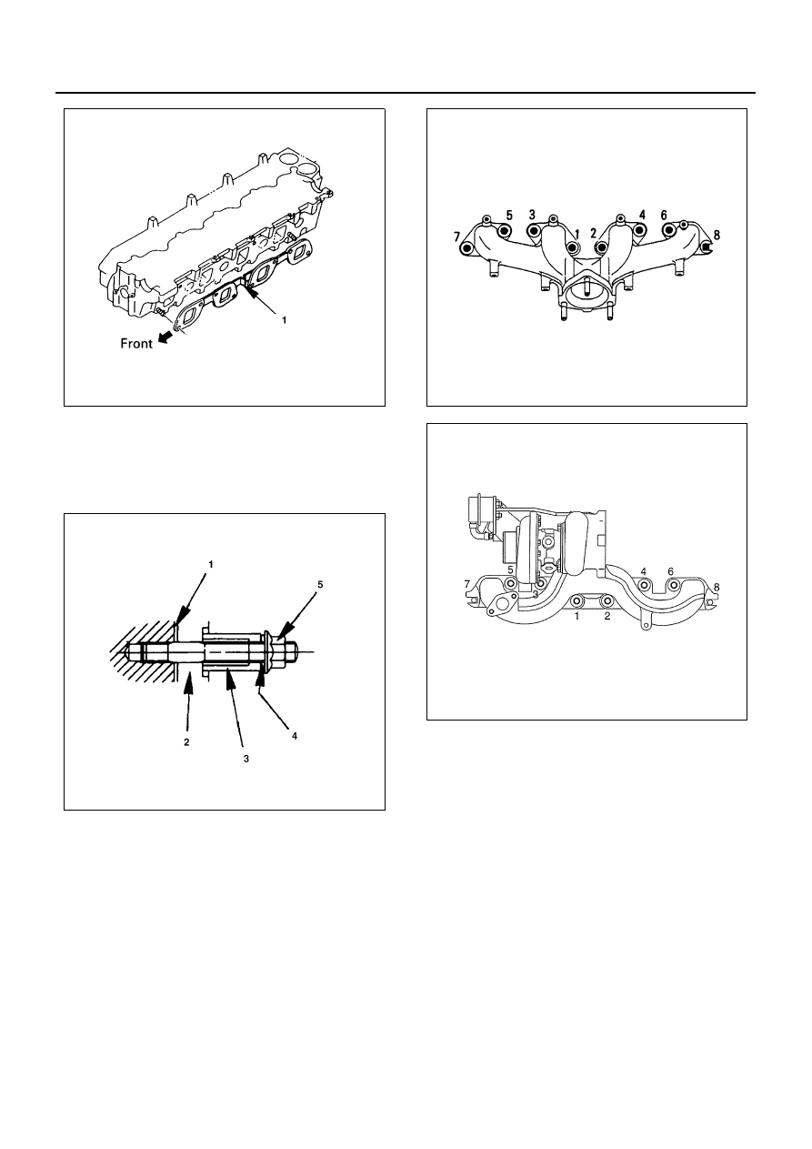
9. Exhaust Manifold

1) Install exhaust manifold gaskets (1), exhaust

manifold (2), distance pieces (3), dish washers
(4) and nuts (5) to the stud bolts shown in the
illustration.

2) Tighten the nuts to the specified torque in the

numerical order shown in the illustration.

Tighten:
Exhaust manifold nut to 34 N

⋅m (3.5 kg⋅m/25 lb⋅ft)

10. Heat Protector

Tighten:
Heat protector bolt to 10 N

⋅m (1.0 kg⋅m/87 lb⋅in)

N6A0507E

N6A0413E

N6A0414E

N6A0510E

ENGINE (4HF1 / 4HF1-2 / 4HE1-TC / 4HG1 / 4HG1-T) 6A3-65

11. Air Conditioning (A/C) Compressor Bracket (If

equipped with A/C)
Tighten fixing bolts to the specified torque.

Tighten:
A/C compressor bracket bolt to 48 N

⋅m (4.9 kg⋅m/35

lb

⋅ft)

12. Inlet Cover/Inlet Case

1) Apply 2 — 3 mm (0.08 — 0.12 in) bead of the

recommended liquid gasket (Three Bond
1207C) or its equivalent on the groove (1) of the
inlet case fitting surfaces shown in the illustra-
tion.

• Clean the inlet case fitting surface of the cylin-

der head.

2) Install the inlet case to the cylinder head.

• Install the inlet case within 7 minutes after ap-

plication of liquid gasket.

• Attach harness clips ((1), (6) and (7)) and tight-

en the inlet cover bolts and nuts to the specified
torque in the numerical order shown in the illus-
tration.

★ marks are located on nut positions.

Tighten:
Inlet cover bolt and nut to 13 N

⋅m (1.3 kg⋅m/9 lb⋅ft)

N6A0415E

N6A0416E

N6A0392E

N6A1500E

6A3-66 ENGINE (4HF1 / 4HF1-2 / 4HE1-TC / 4HG1 / 4HG1-T)

Refer to “CYLINDER HEAD” in this section, install
the remaining parts.

Legend

1. Inlet cover
2. Mounting rubber
3. Bolt

N6A0393E

ENGINE (4HF1 / 4HF1-2 / 4HE1-TC / 4HG1 / 4HG1-T) 6A3-67

OIL FILTER ASSEMBLY

Component

Removal

Preparation

• Disconnect battery ground cable.
• Place a receptacle beneath the oil filter to contain

the drained oil.

1. Oil Pipe
2. Oil Pressure Switch
3. Oil Filter
4. O-ring

Inspection

Oil Filter Cover

1. Check the partial filter orifice for any clogging.
2. Send air into the arrow-marked hole in the illustra-

tion, and check to see if the air blows out from the
small holes in the center sleeve (1).

Installation

1. O-Ring

Apply a coat of engine oil to the O-rings (1) and in-
stall them to the cylinder body.

Legend

1. Oil pipe

3. Oil filter

2. Oil pressure switch

4. O-ring

N6A0515E

N6A0516E


Content   ..  351  352  353  354   ..