Isuzu N-Series. Manual - part 350


  Index      Isuzu     Isuzu N-Series - service repair manual


Search            


Content   ..  348  349  350  351   ..


Isuzu N-Series. Manual - part 350


6A3-52 ENGINE (4HF1 / 4HF1-2 / 4HE1-TC / 4HG1 / 4HG1-T)
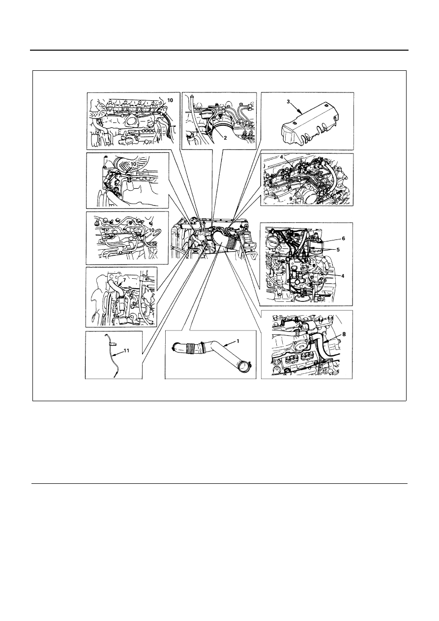
Engine Left Side

Legend

1. Intake air duct

7. Water bypass hose

2. Vacuum hose

8. PCV hose

3. Nozzle cover

9. Injection pipe

4. Leak off pipe

10. Engine harness

5. Fuel pipe

11. Oil level gauge guide tube

6. Fuel filter and bracket 

N6A0477E

ENGINE (4HF1 / 4HF1-2 / 4HE1-TC / 4HG1 / 4HG1-T) 6A3-53

Cylinder Head Side

Removal

Preparation

• Disconnect battery ground cable
• Tilt the cab.
• Drain coolant

Engine Right Side

1. Front Exhaust Pipe

2. Air Conditioning (A/C) Compressor Drive Belt (If

equipped with A/C)

3. A/C Compressor (If equipped with A/C)

1) Disconnect magnetic clutch harness connec-

tor.

2) Dismount the compressor together with the

hoses from the A/C compressor bracket, and
fasten it with a wire to the appropriate location.

Legend

1. Radiator upper hose

8. Valve cap

2. Coolant reserve tank hose/bypass hose

9. Camshaft bearing cap

3. Cylinder head cover

10. Camshaft bearing upper

4. Cylinder head cover gasket

11. Camshaft assembly

5. Glow plug connector

12. Camshaft bearing lower

6. Injection nozzle holder assembly

13. Cylinder head assembly

7. Rocker arm shaft assembly

14. Cylinder head gasket

N6A0482E

6A3-54 ENGINE (4HF1 / 4HF1-2 / 4HE1-TC / 4HG1 / 4HG1-T)

Engine Left Side

1. Intake Air Duct

1) Remove the clips at the connections with the in-

let cover and with the air cleaner.

2) Remove the intake air duct with the connecting

hoses attached.

2. Vacuum Hose
3. Nozzle Cover
4. Leak Off Pipe
5. Fuel Pipe

6. Fuel filter & Bracket 
7. Water Bypass Hose
8. Positive Crankcase Ventilation (PCV) Hose
9. Injection Pipe

1) Loosen the injection pipe sleeve nuts (1).

Do not apply excessive force to the injection
pipes (5).

2) Loosen the injection pipes clips (3).
3) Remove the injection pipe assembly.

Plug the delivery valve holder (2) ports and
nozzle holder (4) ports with caps to prevent the
entry of foreign material.

10. Engine Harness

Disconnect thermometer unit, thermo switch, ta-
chometer sensor and glow plug harness connec-
tors an separate harness from clips.

11. Oil Level Gauge Guide Tube

Remove the guide tube fixing bolt and pull out the
guide tube.

Legend

1. Fuel filter
2. Leak off

N6A0386E

Legend

1. Engine harness

N6A0388E

N6A0389E

ENGINE (4HF1 / 4HF1-2 / 4HE1-TC / 4HG1 / 4HG1-T) 6A3-55

Cylinder Head Side

1. Radiator Upper Hose
2. Coolant Reserve Tank Hose/Bypass Hose
3. Cylinder Head Cover
4. Cylinder Head Cover Gasket
5. Glow Plug Connector
6. Injection Nozzle Holder Assembly

Mark the nozzle holder assemblies fitting positions
by tagging each nozzle holder assembly with the
cylinder number from which it was removed.

7. Rocker Arm Shaft Assembly
8. Valve Cap
9. Camshaft Bearing Cap

10. Camshaft Bearing Upper
11. Camshaft Assembly

12. Camshaft Bearing Lower

Above works refer to “ROCKER ARM SHAFT AS-
SEMBLY AND CAMSHAFT ASSEMBLY” section
in this manual.

13. Cylinder Head Assembly

Loosen the cylinder head bolts in numerical order
a little at a time.

Caution:
Failure to loosen the cylinder head bolts in numerical or-
der a little at a time will adversely affect the cylinder
head lower surface.

14. Cylinder Head Gasket

Caution:
Do not reuse the cylinder head gasket.

Installation

Cylinder Head Side

1. Cylinder Head Gasket

1) When any of the cylinder block, crankshaft,

crankshaft bearing, connecting rod, connecting
rod bearing, and piston is replaced with a new
one, cylinder head gasket thickness ahold be
determined newly.

2) When replacing the cylinder head gasket alone

without replacing any of the parts mentioned in
1) above, the gasket to be used should be the
same grade as the one used before.

3) Correct cylinder head gasket thickness is im-

portant. 
Installing the wrong thickness gasket can result
in greatly reduced engine performance.

4) There are three cylinder head gaskets avail-

able.

Piston Head Projection Measurement

• Select a cylinder head gasket.
• Clean thoroughly the top faces of the piston head

and the cylinder body.

Legend

1. Glow plug connector
2. Injection nozzle holder assembly

N6A0390E

N6A0483

N6A0484E


Content   ..  348  349  350  351   ..