Isuzu N-Series. Manual - part 335


  Index      Isuzu     Isuzu N-Series - service repair manual


Search            


Content   ..  333  334  335  336   ..


Isuzu N-Series. Manual - part 335


6A-82 ENGINE MECHANICAL

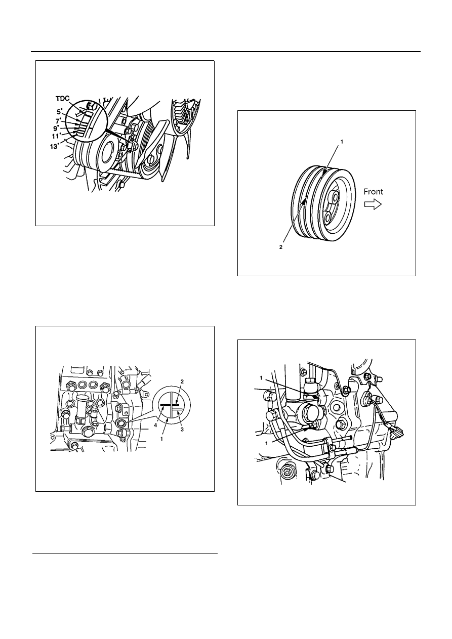
8) Adjust injection pump downward so that the

“8

°” (98EPA) or “9°” (Spec EURO3) comes to

position in the timing check hole. (for 4HE1-TC
only)

Notice:
When ever the injection pump is replaced, be sure to ad-
just the injection timing for the details of the adjustment,
refer to the “SECTION 00 SERVICING: INJECTION
TIMING INSPECTION AND ADJUSTMENT.”

Notice:
In case the crank pulley has two marks as illustrated, (1)
BTDC 49

° mark on the second crest and (2) TDC mark

on the third crest (as viewed from the front side), be sure

to set at the mark (2). (If there are two different marks on
one and same crest, set at the mark which comes sec-
ond when rotated in the normal direction.)
The mark (1) is used when installing the injection pump
for 4HF1-2.

9) Tighten the injection pump bracket nuts and

bolts to the specified torque.

Tighten:
Injection pump bracket nut and bolt (1) to 48 N

⋅m (4.9

kg

⋅m / 35 lb⋅ft)

10) Install the injection pump rear bracket.

Tighten:
Injection pump rear bracket bolt to 48 N

⋅m (4.9 kg⋅m / 35

lb

⋅ft)

11) Install the inspection hole plug.

Tighten:
Inspection hole plug to 48 N

⋅m (4.9 kg⋅m / 35 lb⋅ft)

41. Injection Pump Assembly (4HF1-2 model only)

Legend

1. Timing check hole
2. 8

° Mark

3. 13

° Mark

4. Pointer

N6A0330E

N6A0331E

N6A0055E

N6A0056E

ENGINE MECHANICAL 6A-83

1) Turn the crankshaft to set No.1 cylinder to 49

°

before TDC in its compression stroke.
(49

° is a pump installing alignment angle, not

related to injection timing.)

2) Install O-ring to the injection pump.
3) Apply paint on the 

• (Z) marked side of the in-

jection pump gear.

4) Align the pump bracket mark with the tooth (un-

der side of the pump) just before the 

• (Z)

marked tooth.

5) Insert the pump using the block side of stud bolt

as a guide.

6) After installing the injection pump, remove the

tachometer sensor from the housing, and make
sure that the painted gear is at the center of the
sensor mounting hole.

7) Tighten injection pump clamping bolt and nut to

specified torque:

Tighten:
Bolt to 48 N

⋅m (4.9 kg⋅m / 35 lb⋅ft)

Tighten:
Nut to 24 N

⋅m (2.4 kg⋅m / 17 lb⋅ft)

8) With reference to Injection Timing Check & Ad-

justment, set No. 1 Cylinder to 12

° before its

TDC.

Notice:
In case the crank pulley has two marks as illustrated (1),
BTDC 49

° mark on the second crest and (2) TDC mark

on the third crest (as viewed from the front side), be sure
to set at the mark (2). (If there are two different marks on
one and same crest, set at the mark which comes sec-
ond when rotated in the normal direction.)

42. Injection Timing Check (4HF1-2 model only)

1) Set No. 1 Cylinder to the TDC in the compres-

sion stroke.

N6A0334E

N6A0335E

N6A0336E

N6A0055E

6A-84 ENGINE MECHANICAL

2) Disconnect Injection Pipe.
3) Put down Wax CSD lever, insert a spacer 10 —

20 mm (0.39 — 0.47 in) thick between the
plunger and adjust bolt, and cancel the Wax
CSD.

4) Remove the pump rear plug, connect a dial

gage and set the lift at 1 mm (0.039 in).
Special Tool
Measuring device: 5-8840-0145-0

5) Set the crankshaft damper pulley TDC mark to

the pointer or 45

° before TDC.

6) Set the dial gage to the “0” position.

7) Turn the crankshaft leftwise and rightwise a lit-

tle and make sure that the needle stays in the
“0” position.

8) Turn the crankshaft in the normal direction and

read the measuring device’s indication at the
12

° before TDC position.

Notice:
As there is no 12

° mark, set midway between the 11°

and 13 marks.
Standard value: 0.5 mm (0.0197 in)

43. Injection Timing Adjustment (4HF1-2 model only)

If injection timing is out of the specified range, fol-
low the following procedure for adjustment:
1) Loosen injection pump fixing nuts and bracket

bolt.

2) Adjust the mounting angle of injection pump:

• If injection timing is too fast, bring the injec-

tion pump closer to the engine.

• If injection timing is too slow, put the injec-

tion pump more distant from the engine.

Legend

1. Water house
2. Wax CSD
3. Spacer
4. Lever

N6A0057E

N6A0058E

N6A0059E

N6A0060E

ENGINE MECHANICAL 6A-85

3) When the dial gage has indicated the specified

value, tighten the fixing nuts and bolt to speci-
fied torque:

Tighten:
Nut to 24 N

⋅m (2.4 kg⋅m / 17 lb⋅ft)

Tighten:
Bolt to 48 N

⋅m (4.9 kg⋅m / 35 lb⋅ft)

4) Disconnect the dial gage, install and tighten the

plug to specified torque. (Make sure of a copper
washer being attached to the plug)

Tighten:
Pump rear plug to 17 N

⋅m (1.7 kg⋅m / 12 lb⋅ft)

5) Release the wax CSD and connect the injec-

tion pipe.

Tighten:
Pipe sleeve to 29 N

⋅m (3.0 kg⋅m / 22 lb⋅ft)

Notice:
If there are two marks on the crank pulley, the front side
of mark is for setting BTDC 49

° and the rear side of mark

is for setting TDC.

44. Engine Foot

Tighten:
Engine foot bolt to 51 N

⋅m (5.2 kg⋅m / 38 lb⋅ft)

45. Generator

Notice:
Before tightening the generator securely, tighten it tem-
porarily in advance after adjusting the fan belt. Put the
lower fixing bolt through from the rear side and tighten it
with the nut on the front side as shown in the illustration.

46. Fan Belt

Check the drive belt tension.
Depress the drive belt mid-portion with a 10 kg (22
lb / 98 N) force.

Check the drive belt for cranking and other dam-
age.

Legend

1. Bolts
2. Nuts

N6A0342E

Drive Belt Deflection

mm (in)

New belt

8 — 12 (0.31 — 0.47)

Reuse belt

10 — 14 (0.39 — 0.55)

N6A0343E

N6A0344E


Content   ..  333  334  335  336   ..