Isuzu N-Series. Manual - part 306


  Index      Isuzu     Isuzu N-Series - service repair manual


Search            


Content   ..  304  305  306  307   ..


Isuzu N-Series. Manual - part 306


00-36 SERVICE INFORMATION
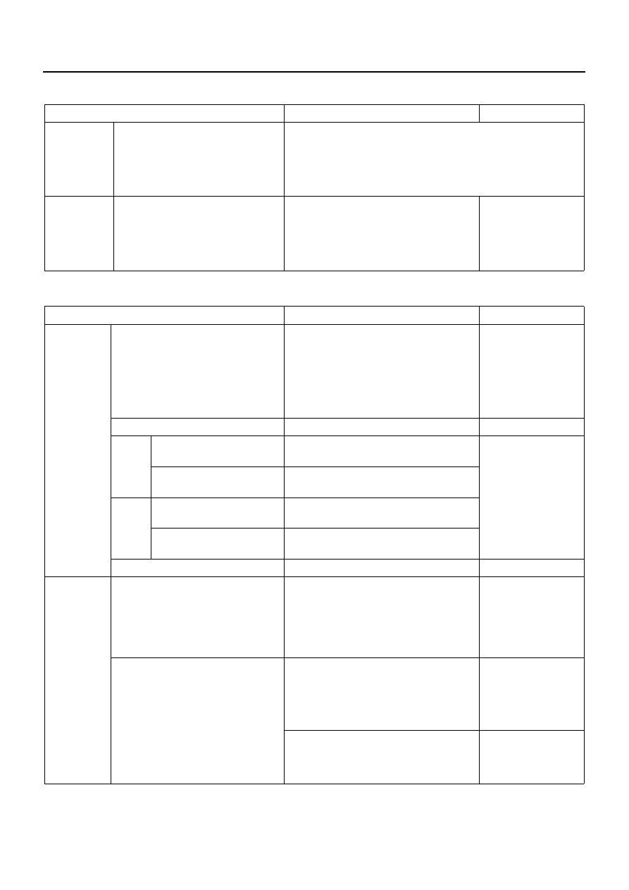
Fuel System

Engine Electrical

Item

Service Standard

Service Limit

Fuel Feed 
Pump

Suction capacity

The suction must be completed in 25 times or less.

Priming Pump Speed: 
Pipe Inside Diameter: 
Suction Pipe Length: 
Suction Height: 

60 — 100 times/minute
8mm (0.31in)
2,000mm (78.7 in)
1,000mm (39.4in)

Injection 
Nozzle

Spray Condition

• The spray must be fine and uniform.
• The injection must be directed in the 

center direction with no stray spray.

• The spray from each nozzle hole 

must be uniform

Item

Service Standard

Service Limit

Generator

Ball bearing

When it doesn’t 
rotate smoothly or is 
giving out an abnor-
mal sound, or when 
there is an oil leak 
from the seal, 
replace it.

Slip Ring Diameter 

mm (in)

Nominal size 31.6 (1.244)

30.6

Rotor

Coil Resis-
tance 

Nominal resistance 12.6

When the resis-
tance differs largely 
from the standard 
value, or when a 
poor insulation is 
found, replace it.

Coil Insulation 
Resistance 

M

1 or more 

(500 volt megger tester)

Stator

Coil Resis-
tance

Nominal resistance 0.17 

(Between coil end and each coil end)

Coil Insulation 
Resistance 

M

1 or more

(500 volt megger tester)

Brush Length 

mm (in)

Nominal size 20 (0.79)

6 (0.24)

IC Voltage 
Regulator

Rectifier

The rectifier is normal when there is 
continuity with the tester - terminal con-
nected to “B” (battery) terminal and the 
+ terminal to the rectifier holder, and 
when there is no continuity with their 
connections reversed.

When there is conti-
nuity in both direc-
tions, or when there 
is no continuity in 
both directions, 
replace the rectifier.

Battery Power 

V <4HF1 / 4HF1-2 / 4HG1 / 4HG1-T>

LR 250 — 504 (24V - 60A)

28 — 29

LR 250 — 508B (24V - 50A)

28 — 29

DENSO (12V - 35A)

27.8 — 28.8

<4HE1-TC>

LR 250 — 510 (24V - 50A)

28 — 29

LR 180 — 510 (12V - 80A)

14.1 — 14.7

SERVICE INFORMATION 00-37

IC Voltage 
Regulator

Output Current

A

1300 

rpm

2000 

rpm

4000 

rpm

<4HF1 / 4HF1-2 / 4HG1 / 4HG1-T>

LR 250 —

504

18

35

53

LR 250 —

508B

15

32

46

DENSO

12

18

37

<4HE1-TC>

LR 250 —

510

15

32

43

LR 180 —

510

25

58

82

Pulley Ratio 
(Crankshaft/Generator)

175 / 82

Vacuum 
Pump

Pump Housing Inside 
Diameter 

mm (in)

60.0 — 60.1 (2.362)

(Reference)

Vane Length 

mm (in)

14.2 — 15.2 (0.559 — 0.598)

(Reference)

Performances

1,000 rpm 13 sec or less

Time required for the pressure to 
get to -66.7kPa (-500mmHg / -
9.7psi).

1,000 rpm 35 sec or less

(LR 180 — 510 only)

5,000 rpm 4 sec or less

5,000 rpm 10 sec or less

(LR 180 — 510 only)

Oil Viscosity: SAE 30

Oil Temperature: 70 

± 5°C (158 ± 

9

°F)

Oil Pressure: 441kPa (4.5 kg 

/ cm

2

 / 64psi)

Tank Capacity: 7,000cc (427 

cu

⋅in)

Check Valve

• Apply 98 — 490 kPa (1 — 5 kg/cm

2

 14-71 psi) compressed 

air to pump side of the check valve.

• Check for air leakage from the check valve.
• If there is air leakage, the check valve must be replaced.

Starter

Commutator Run-Out

mm (in)

0.05 (0.002) or less

0.2 (0.008)

Commutator Outside 
Diameter 

mm (in)

36.5 (1.437)

35.5 (1.398)

Mica Segment Depth

mm (in)

0.5 — 0.8 (0.020 — 0.031)

0.2 (0.008)

Brush Length

mm (in)

15.0 (0.591)

10.5 (0.413)

Brush Spring Tension

N (kg /

lb)

24.5 — 34.3 (2.5 — 3.5 / 5.5 — 7.7)

Item

Service Standard

Service Limit

00-38 SERVICE INFORMATION

Starter

Load Characteristics

Terminal Voltage 

V

18.55

Load Current 

A

250

Torque

N

⋅m

(kg

⋅m /

lb

⋅ft)

14.2 (1.45 / 10.5) or more

Speed

rpm

860

Preheating 
system 
(QOSII)

Time required for the
glow indicator to light up

sec

3.5

After the key switch is turned to ON 

position without engine turned.

Time required for the 
source voltage to be 
supplied to the glow 
plug

sec

18

After the key switch is turned to ON 

position without engine turned.

Glow Relay Coil Resis-
tance

Nominal resistance 51.5

Thermo Switch Operat-
ing Temperature 

°C (°F) OFF → ON: 7 — 13 (44.6 — 55.4)

ON 

→ OFF: Less 3 (37.4)

Glow Plug Continuity

If no continuity 
exists, must be 
replaced.

Item

Service Standard

Service Limit

Terminal

ACC

B

ON

ST

B

1

P

1

P

2

W

W

LOCK

ACC

ON

START

N6A1414E

SERVICE INFORMATION 00-39

SERVICING

Servicing refers to general maintenance procedures to
be performed by qualified service personnel.

Model Identification

Engine Serial Number

The engine number is stamped on the front left hand
side of the cylinder body.

Air Cleaner

Dust Indicator

1. The dust indicator is installed to the air cleaner. (for

Australia and GCC) 
Inspect the dust indicator. If the indicator plate is
red, the air cleaner element must be cleaned or re-
placed.

2. Clean the air cleaner element once and reinstall it. 

Press the dust indicator button to clear the dust in-
dicator.

Dry Type Washable Paper Element

Element cleaning procedures will vary according to the
condition of the element.

Dust Fouled Element

Rotate the element with your hand while applying com-
pressed air to the inside of the element. This will blow
the dust free.
Compressed air pressure must not exceed 686 kPa (7
kg/cm

2

 / 99.6 psi).

Legend

1. Engine type
2. Engine number

N6A0006E

Legend

1. Dust indicator
2. Red color

N6A0007E

N6A0008E


Content   ..  304  305  306  307   ..