Isuzu N-Series. Manual - part 300


  Index      Isuzu     Isuzu N-Series - service repair manual


Search            


Content   ..  298  299  300  301   ..


Isuzu N-Series. Manual - part 300


00-12 SERVICE INFORMATION

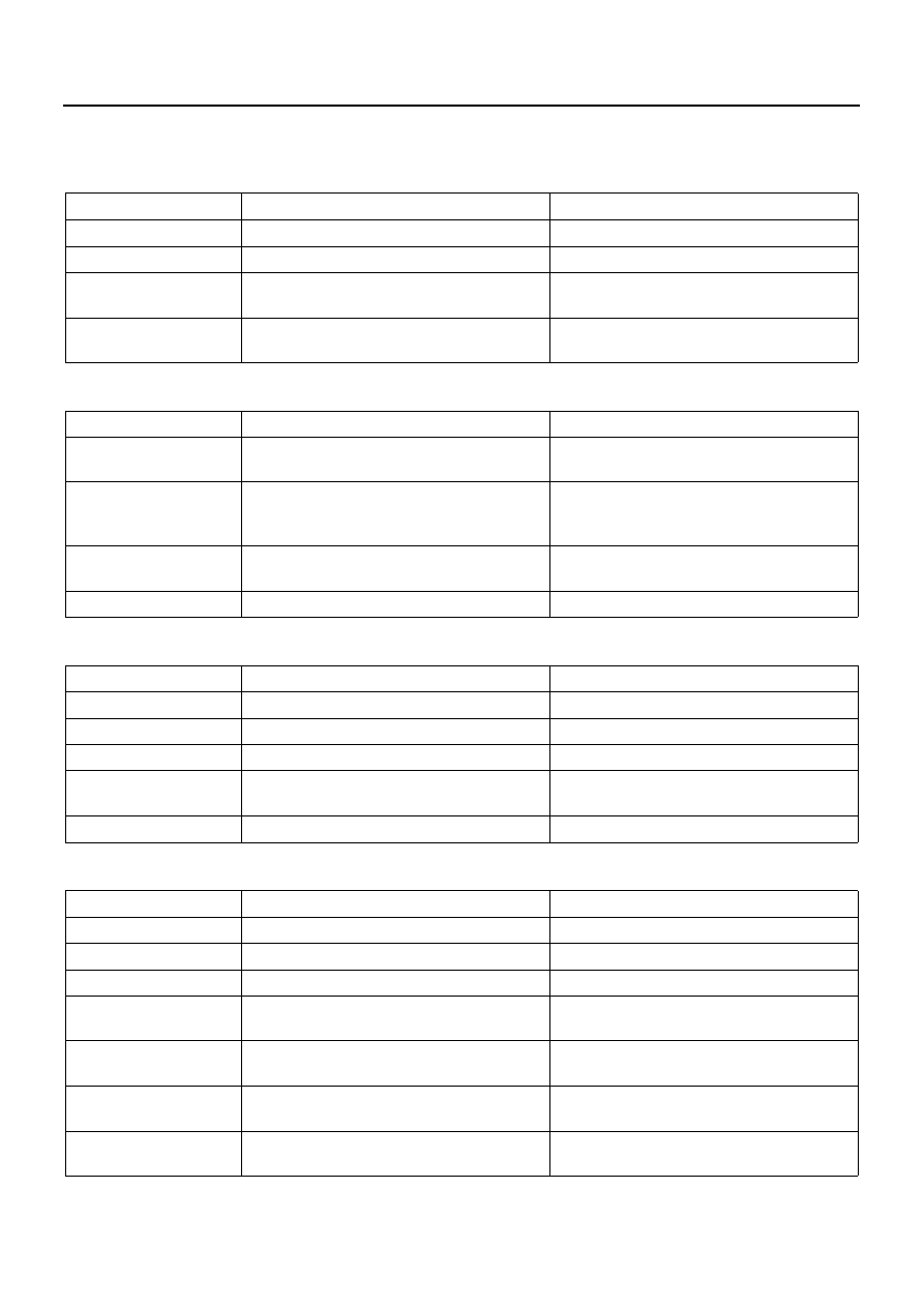
Abnormal Engine Noise

1. Engine Knocking

Check to see that the engine has been thoroughly warmed up before beginning the troubleshooting procedure.

2. Gas Leakage Noise

3. Continuous Noise

4. Slapping Noise

Check point

Possible cause

Correction

Fuel

Fuel unsuitable

Replace the fuel

Fuel injection timing

Fuel injection timing improperly adjusted

Adjust the fuel injection timing

Injection nozzle

Improper injection nozzle starting pressure 
and spray condition

Adjust or replace the injection nozzle

Compression pressure

Blown out head gasket

Broken piston ring
Replace the head gasket or the piston ring

Check point

Possible cause

Correction

Exhaust pipes

Loosely connected exhaust pipes
Broken exhaust pipes

Tighten the exhaust pipe connections 
Replace the exhaust pipes

Injection nozzles and/
or glow plugs

Loose injection nozzles and /or glow plugs  Replace the washers

Tighten the injection nozzles and/or the 
glow plugs

Exhaust manifold

Loosely connected exhaust manifold and/
or glow plugs

Tighten the exhaust manifold connections

Cylinder head gasket

Damaged cylinder head gasket

Replace the cylinder head gasket

Check point

Possible cause

Correction

Fan belt

Loose fan belt

Readjust the fan belt tension

Cooling fan

Loose cooling fan

Retighten the cooling fan

Water pump bearing

Worn or damaged water pump bearing

Replace the water pump bearing

Alternator or vacuum 
pump

Defective alternator or vacuum pump

Repair or replace the alternator or the vac-
uum pump

Valve clearance

Clearance improperly adjust

Adjust the valve clearance

Check point

Possible cause

Correction

Valve clearance

Valve clearance improperly adjusted

Adjust the valve clearance

Rocker arm

Damaged rocker arm

Replace the rocker arm

Flywheel

Loose flywheel bolts

Retighten the flywheel bolts

Crankshaft and thrust 
bearings

Worn or damaged crankshaft and/or thrust 
bearings

Replace the crankshaft and/or the thrust 
bearings

Crankshaft and con-
necting rod bearings

Worn or damaged crankshaft and/or con-
necting rod bearings

Replace the crankshaft and/or the con-
necting rod bearings

Connecting rod bush-
ing and piston pin

Worn or damaged connecting rod bushing 
and piston pin

Replace the connecting rod bushing and/
or the piston pin

Piston and cylinder 
liner

Worn or damaged piston and cylinder liner 
Foreign material in the cylinder

Replace the piston and the cylinder liner

SERVICE INFORMATION 00-13

Engine Cooling Trouble

Condition

Possible cause

Correction

Engine overheating

Low coolant level

Replenish

Thermo unit faulty

Replace

Faulty thermostat

Replace

Faulty coolant unit

Repair or replace

Clogged radiator

Clean or replace

Faulty radiator cap

Replace

Low engine oil level or use of improper 
engine oil

Replenish or change oil
Replenish

Damaged cylinder head gasket

Replace

Clogged exhaust system

Clean exhaust system or replace faulty 
parts

Loose fan belt

Adjust

Excessive fuel injected

Adjust

Improper injection timing

Adjust

Engine overcooling

Faulty thermostat

Replace

Too long engine warm-
up time

Faulty thermostat

Replace

Thermo unit faulty

Replace

00-14 SERVICE INFORMATION

Starter Motor Does Not Stop

N6A0005E

SERVICE INFORMATION 00-15

MAIN DATA AND SPECIFICATIONS

Main Data and Specifications

Engine Model

4HF1

4HF1-2

Item

Engine type

Four-cycle, overhead camshaft, water cooled

Combustion chamber type

Direct injection

Cylinder liner type

Dry liner, special compound metal

Timing drive system

Gear drive

No. of cylinders — Bore 

× 

stroke

mm (in)

4 — 112 

× 110 (4 — 4.41 × 4.33)

No. of piston rings

Compression rings: 2, Oil ring: 1

Total piston displacement

cm

3

 (in

3

)

4334 (264.5)

Compression ratio 

to : 1

19

Compression pressure 

3,040 (31/441) — 200

3,226 (32.9/468) — 200

kPa (kg / cm

2

 / psi) — rpm

Fuel injection order

1 — 3 — 4 — 2

Fuel injection timing 
(BTDC) 

deg

8

12

Specified fuel type

SAE No. 2 diesel fuel

Idling speed rpm

550 — 600

575 — 625

Valve system

Valve clear-
ances (At cold):

Intake

mm (in)

0.4 (0.016)

Exhaust

mm (in)

0.4 (0.016)

Valve timing (At valve clearances 0.4
mm (0.016 in))

Intake valves 

Open at 
(BTDC) 

deg

18

Close at 
(ABDC) 

deg

50

Exhaust valves 

Open at 
(BBDC) 

deg

51

Close at 
(ATDC)

deg

17

Fuel system

Injection pump type

Bosch in-line type with auto-

matic timer

Bosch “VE” distributor with 

automatic timer

Plunger outside diameter 

mm (in)

9.5 (0.374)

12 (0.472)

Plunger lift 

mm (in)

11.0 (0.433)

2.8 (0.110)

Governor type

RLD-F mechanical (Variable 

speed)

Half all speed governor

Automatic timer type

SCDM, centrifugal, flyweight

Hydraulic speed sensing type

Fuel feed pump type

Piston

Vane


Content   ..  298  299  300  301   ..