Isuzu N-Series. Manual - part 281


  Index      Isuzu     Isuzu N-Series - service repair manual


Search            


Content   ..  279  280  281  282   ..


Isuzu N-Series. Manual - part 281


HSA (HILL START AID) 5A5-3
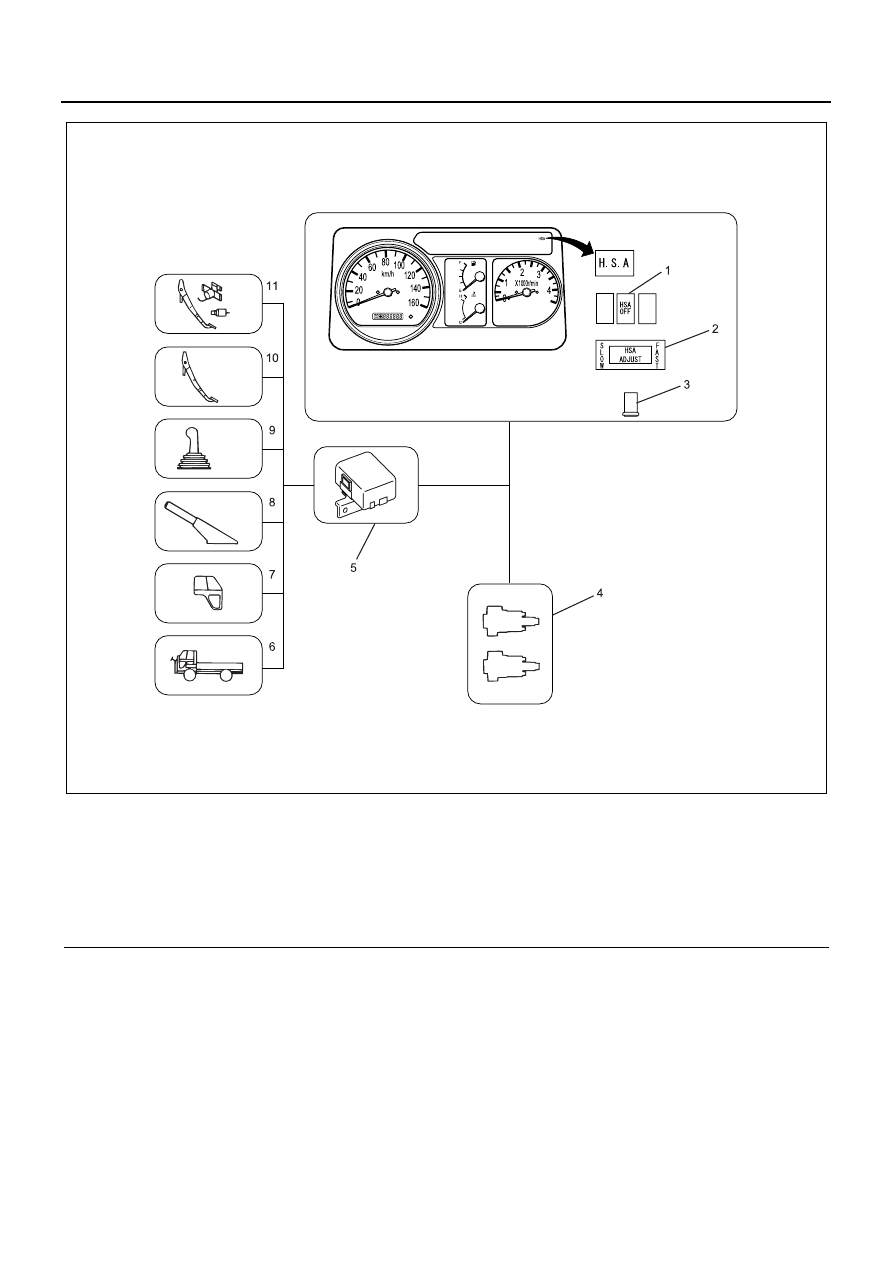
Legend

1. HSA off switch
2. HSA adjust switch
3. HSA reset switch
4. HSA valve
5. Control unit buzzer built-in
6. Speed sensor

7. Door switch
8. Parking brake switch
9. Neutral switch

10. Stop lamp switch

11. Clutch stroke sensor/clutch fluid pressure sensor

N5A3064E

5A5-4 HSA (HILL START AID)

Part Location Diagram

Legend

1. HSA indicator lamp
2. HSA off switch
3. HSA caution plate
4. HSA adjust switch
5. HSA reset switch
6. Stop lamp switch

7. Clutch stroke sensor
8. Clutch fluid pressure switch
9. HSA control unit

10. Parking switch

11. Door switch

N5A3065E

HSA (HILL START AID) 5A5-5

Legend

1. HSA off switch
2. HSA reset switch, HSA adjust switch
3. Door switch (RH)
4. Parking brake switch
5. Speed sensor
6. Neutral switch

7. Door switch (LH)
8. HSA control unit
9. HSA valve

10. Clutch sensor/clutch fluid pressure switch

11. HSA indicator lamp

12. Stop lamp switch

HSA Control Unit

The HSA control unit activates the HSA valve to hold/re-
lease the brake fluid pressure based on the input signal
from each switch and sensor. When a malfunction oc-
curs in the system, it activates the built-in buzzer and
blinks the HSA indicator lamp to indicate the trouble
code.
Also the system has the alarm functions as follows:

1. Door open alarm when HSA operating

When the door is opened while the HSA is operat-
ing; it triggers the built-in buzzer and blink the HSA
indicator lamp.

2. HSA long-time operation alarm

When the HSA have operated for more than 8 min-
utes; it triggers the built-in buzzer and blink the
HSA indicator lamp.

3. Vehicle motion alarm

When the vehicle speed reaches aprrox. 1.5km/h
(1 mph) while HSA operating; it triggers the built-in
buzzer and blink the HSA indicator lamp. (Howev-
er, the HSA is released when the vehicle speed
reaches 5km/h (3 mph).)

N5A3004E

N5A3066E

5A5-6 HSA (HILL START AID)

HSA Valve

The HSA valve is located in the pipe route between the
master cylinder and the wheel cylinder, and it is driven
by the HSA control unit output (ON/OFF).

Clutch Sensor

The clutch sensor is installed to the clutch pedal bracket
and changes the voltage being input to the HSA control
unit by sensing the amount of clutch pedal depressed.
This voltage is one of the signals to control the HSA op-
eration/release.

Clutch Fluid Pressure Switch

The clutch fluid pressure switch is off the contact with
the clutch pedal fully engaged, and it contacts the point
with the clutch pedal depressed (clutch disengaged).
The HSA system memorizes the clutch meeting point
(engaging point) to release the brake force at that point.
However, the meeting point is gradually raised as the
driven plate wears, resulting the brake force be released
before the clutch engages.
To prevent this, the HSA has a follow-up function auto-
matically to co-op with the clutch wear.

Clutch-wear Automatic Follow-up Mechanism

The clutch fluid pressure switch is installed to the clutch
master cylinder, and it turns ON with the clutch pedal de-
pressed, and turns OFF with the clutch pedal released.
Positional relationship between the stroke point where
the HSA is released and this clutch fluid pressure switch
OFF position is constant regardless the degree of clutch
disc wear.
Utilizing this characteristic, the HSA can follow-up the
release point automatically even when the fluid pressure
switch OFF point is shifted.

N5A3006E

N5A3007E

N5A3008E


Content   ..  279  280  281  282   ..