Isuzu N-Series. Manual - part 278


  Index      Isuzu     Isuzu N-Series - service repair manual


Search            


Content   ..  276  277  278  279   ..


Isuzu N-Series. Manual - part 278


5A4-86 ABS/ASR

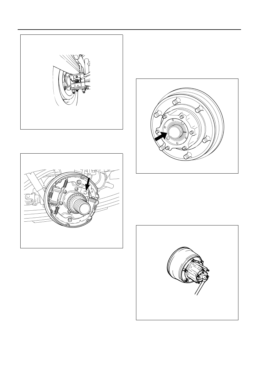
7. Rear speed sensor

• Remove the speed sensor installing bolt, and

take out from the sensor bracket.

Installation

CAUTION:

• Grommet in the back plate must be installed se-

curely.

• Bearing lock nut must be installed with its slit sur-

face facing outside.

1. Rear speed sensor

• Tighten the speed sensor installing bolt.

Tighten:

Bolt to 22 N

⋅m (2.2 kg⋅m / 16.2 lb⋅ft)

2. Harness connector

• Connect the harness connector.

3. Inner bearing

• Install the inner bearing.

4. Inner oil seal

• Install the inner oil seal.

5. Hub and drum assembly

• Install the hub and drum assembly.

6. Outer bearing, hub, bearing lock nut

• Install the outer bearing, hub, and bearing lock

nut.

Rear hub bearing preload adjustment

• Rotate the hub to the left and right several times

to make it seated.

• Tighten the bearing lock nut till the hub no long-

er be turned. Then, back off to a degree that the
hub rotates easily.

Special tool:
Wrench: 9-8522-1180-0

• Attach a spring balance to the wheel pin. While

pulling it tangentially, tighten the bearing nut so
that the spring balance reading shows the spec-
ified value when the hub starts rotation.

N5A2063E

N5A2064E

N5A2065E

N5A2066E

ABS/ASR 5A4-87

Tighten:

Starting to 42 — 52 N (4.3 — 5.3 kg / 9.4 — 11.7 lb)

• After adjusting the starting torque, move the

hub to the right and left side several times to
make sure the value is correct.

• With the preload adjusted, match the lock cut-

out center point of the axle case screw part with
nearest ruling of the bearing lock nut. If it does
not, rotate the nut in the tightening direction to
match.

7. Lock washer, outer oil seal, axle shaft

• Install the pawl of the lock washer to the lock

cutout of the axle case screw part securely, and
tighten the bearing nut and the lock washer with
the lock bolt.

• Apply grease to the circumference of the outer

oil seal inner lip, and install the outer oil seal.

• Install the axle shaft.

Install to the rear hub stud part through the spe-
cial washer with the flange nut.

Tighten:

Flarge nut to 49 N

⋅m (5.0 kg⋅m / 36.1 lb⋅ft)

N5A2067E

N5A2068E

N5A2069E

5A4-88 ABS/ASR

Inspection

RL Wheel Speed Sensor Output Check Procedure
Check flow C-1-3

Step

Action

Value

YES

NO

1

1. Turn the starter switch OFF.
2. Disconnect the connector of the EHCU.
3. Jack-up the vehicle to lift the front wheels

off the floor.

4. Connect a 120

Ω resistance between the

J-177 connector terminal 34 and the
ground.

5. Apply a 9 — 16V voltage to the J-177

connector terminal 22.

6. Measure the DC voltage between the B-

177 connector terminal 34 and the
ground while turning the RL wheel half
turn/sec.

Is the value within specified value?

0.2 — 4.5V

Go to Step5

Go to Step2

2

1. Turn the starter switch OFF.
2. Disconnect the RL wheel speed sensor

connector J-149.

3. Connect a 120

Ω resistance between the

J-149 connector terminal 2 and the
ground.

4. Apply a 9 — 16V voltage to the J-149

connector terminal 1 (sensor side).

5. Measure the DC voltage between the J-

149 connector terminal 2 and the ground
while turning the RL wheel half turn/sec.

Is the value within specified value?

0.2 — 4.5V

Go to Step3

Go to Step4

3

Repair the circuit for open/short circuit, and
the connector for improper connection
between the connector of EHCU and the sen-
sor connector.

Is this step completed?

Go to Step5

4

Replace the RL wheel speed sensor.

Is this step completed?

Go to Step5

5

1. Install all the components, and check that

those are installed properly.

2. Clear the DTC.

Is this step completed?

Go to “Diagnostic 

basic flow”.

Go to Step5

ABS/ASR 5A4-89

Legend

1. Battery (12V)
2. Tester
3. Resistance
4. Speed sensor

N5A2070E


Content   ..  276  277  278  279   ..