Isuzu N-Series. Manual - part 261


  Index      Isuzu     Isuzu N-Series - service repair manual


Search            


Content   ..  259  260  261  262   ..


Isuzu N-Series. Manual - part 261


5A4-18 ABS/ASR

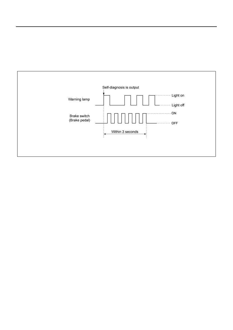
How to Clear Diagnosis Trouble Code (DTC)

DTCs stored in the EHCU will not be erased automati-
cally upon repair. Clear the DTCs using either of the fol-
lowing procedure:

1. Input the brake switch ON/OFF signal for six times

within three seconds while self-diagnosis result is
being output.

2. Use Tech 2 to clear.

CAUTION:

• After performing the DTC clear procedure, ensure

that it is cleared.

• If the step 1 does not work, perform with the step2.

Precautions During Diagnosis

At general baintenance
Adhere the following precautions when servicing and di-
agnosing of the ABS/ASR and other vehicle control sys-
tems.

• When performing electric-arc welding on the vehi-

cle, disconnect the EHCU connector before start-
ing welding work.

• Do not connect/disconnect the EHCU connector

when the starter switch is ON.

• The EHCU is a non-disassembled part. Do not

loosen the bolts and plugs of the EHCU.

• Be especially careful not to allow dirt, dust or me-

tallic powder to get into the hydraulic circuit during
checking and servicing the brake components.

• When only rear wheels are rotated using dram

tester or jack-upped for inspection, the ABS judges
it as sensor fault and illuminates the ABS warning
lamp. This indicates no fault in the system. Erase
the ABS diagnosis code after repair. Turn the start-
er switch to ON again, to make sure that the ABS
warning lamp does not come on.

When servicing computer system
Extreme care is required to avoid overcurrent to the
EHCU circuit. Do not ground to or apply voltage to the
EHCU without careful consideration while checking
open/short circuit. Use only the circuit tester having high
internal resistance or the special tool described in this
section to check those circuit. Do not connect/discon-
nect the power supply to the EHCU when the starter

switch is ON. Be sure to turn the starter switch to OFF
before disconnecting/connecting the battery cable, the
fuse, or the connector.
When replacing EHCU
The EHCU body fault rarely occurs, but more cases are
falsely identified as EHCU trouble, as it happened to be
corrected when replacing the EHCU but the fact is most-
ly secondary failure caused by the harness-side trouble
(such as short circuit) or undetectable cause due to in-
termittent trouble. Therefore, before replacing the EH-
CU, check if overcurrent is applied to the EHCU as well
as improper connection of the connectors.
Intermittent trouble
Intermittent troubles are mostly caused by temporally
disconnection of the harnesses and connectors. If a
trouble occurs, check the related circuit in the following
procedure. 

1. Check for misconnection of the connector. Also

check for improper connection of the connector ter-
minal.

2. Check for deformation and damage of the terminal.

If deformed or damaged, correct and reconnect it
securely.

3. Simulated open circuit is also suspected. Check

the circuit by shaking the harness in a degree that
does not damage the harness.

Test run of vehicle with ABS problem
Trouble cause of the problem appeared as ABS warning
lamp illumination, can be identified with “Diagnostic pro-
cedure with illumination pattern”. However for the prob-
lem that can solely be identified by the driver as trouble

N5A2017E

ABS/ASR 5A4-19

symptoms, the following procedure is necessary to iden-
tify the trouble cause by reproducing the trouble symp-
tom with test run the vehicle.

1. Start the engine, and make sure that the ABS

warning lamp goes off. (If the lamp does not go off,
read the DTC and identify the trouble part.)

2. Slowly start the vehicle and run at 30 km/h (19

mph) or more for three minutes, then apply the
brake to stop the vehicle completely. Start the ve-
hicle again and accelerate to 30 km/h (19 mph) or
more. Repeat this operation a least three times.

3. Next, start the vehicle and accelerate to 40 km/h

(25 mph) or more, and then abruptly apply the
brake to activate the ABS, till stop the vehicle.

4. If the warning lamp comes on during the test run,

check the DTC and inspect the vehicle according
to the DTC. If no DTC appeared, or the warning
light does not come on, reproduce the condition of
the trouble occurrence claimed by the customer as
much as possible.

5. If DTC appeared or trouble symptom is found, per-

form the appropriate inspection according to the di-
agnostic procedure.

Check after repair
Upon completion of repair, turn the starter switch to OFF
and then start the engine to make sure each lamp goes
off. Next, run the vehicle at 30 km/h (19 mph) or more for
1 minute, and check that the lamp does not come on.

Brake basic inspection

Ground check

Step

Action

Value

YES

NO

1

Is the brake fluid level correct?

Go to Step2

Replenish fluid. 

Go to Step2

2

Is fluid leaked?

Go to Step3

Repair. Go to 

Step3

3

Does the vacuum booster operate normally?

Go to Step4

Repair. Go to 

Step4

4

Is the brake pad and rotor normal?

Go to Step5

Repair. Go to 

Step5

5

Install all the components, and check that
those are installed properly.

Is this step completed?

End.

Go to Step5

Step

Action

Value

YES

NO

1

Are all the ground point related to ABS OK?

Go to Step2

Repair. Go to 

Step2

2

Install all the components, and check that
those are installed properly.

Is this step completed?

End.

Go to Step2

5A4-20 ABS/ASR

Diagnostic basic flow

Function Check

EHCU Connector Pin Arrangement

Step

Action

Value

YES

NO

1

1. Complaint from the customer
2. Interview to the customer.
3. Perform the basic inspection. (Refer to

“Brake basic inspection”.)

Is Tech 2 required?

Go to Step2

Go to Step3

2

Check DTC.

Is DTC appeared?

Go to Step5

Go to Step4

3

Check DTC (with warning lamp illumination
pattern).

Is DTC appeared?

Go to Step5

Go to Step4

4

Test run the vehicle.

Does the warning lamp come on?

Go to Step5

Refer to “List of 

trouble symp-

tom”.Go to Step5

5

1. Repair the trouble part.
2. Clear the DTC.
3. Check the ABS warning lamp for illumina-

tion pattern with the ignition switch ON.

4. Test run the vehicle.

Is the trouble appeared again?

Repeat the “Diag-

nostic basic flow” 

if the trouble 

appeared again 

(with trouble 

symptom or DTC). 

Go to Step1

Go to Step6

6

1. Install all the components, and check that

those are installed properly.

2. Clear the DTC.

Is this step completed?

End.

Go to Step6

N5A2018E

ABS/ASR 5A4-21

Terminal

Mark

Signal name

Wire color

1

VALVE GND

ECU system ground (body ground 0V)

BLK

2

VALVE+B

Solenoid valve power supply

RED

3

IG-KEY

ECU system power supply

BLK/YEL

4

DIAG

Diagnosis entry

WHT/GRN

5

SW; ASR OFF

ASR cut switch (ASR only)

BLU

6

ABS W/L

ABS warning lamp output

WHT/VIOLET

7

NC

Not available

8

NC

Not available

9

NC

Not available

10

FR SIG

FR wheel speed signal (magnetic pickup sensor)

PNK

11

FR GND

FR wheel speed signal GND

BLU

12

RR GND

RR wheel speed signal GND

WHT

13

NC

Not available

14

CAN-H

CAN Hi input

BLU/WHT

15

CAN-L

CAN Lo input

BLU

16

BRK SW

Brake switch input signal

GRN

17

NC

Not available

18

NC

Not available

19

NC

Not available

20

NC

Not available

21

RR SIG

RR wheel speed signal

RED

22

RL SIG

RL wheel speed signal

BLU

23

MOTOR GND

Motor ground (body ground 0V)

BLK

24

MOTOR+B

Motor power supply

RED

25

NC

Not available

26

CAN-H

CAN Hi input

BLU/WHT

27

CAN-L

CAN Lo input

BLU

28

NC

Not available

29

ALDL

J1850 Class 2 communication

WHT/BLK

30

ASR W/L

ASR warning lamp output (ASR only)

WHT/BLU

31

NC

Not available

32

FL SIG

FL wheel speed signal (magnetic pickup sensor)

VIOLET

33

FL GND

FL wheel speed signal GND

RED/BLK

34

RL GND

RL wheel speed signal GND

YEL


Content   ..  259  260  261  262   ..