Isuzu N-Series. Manual - part 256
EXHAUST BRAKE 5E-5
UNIT REPAIR
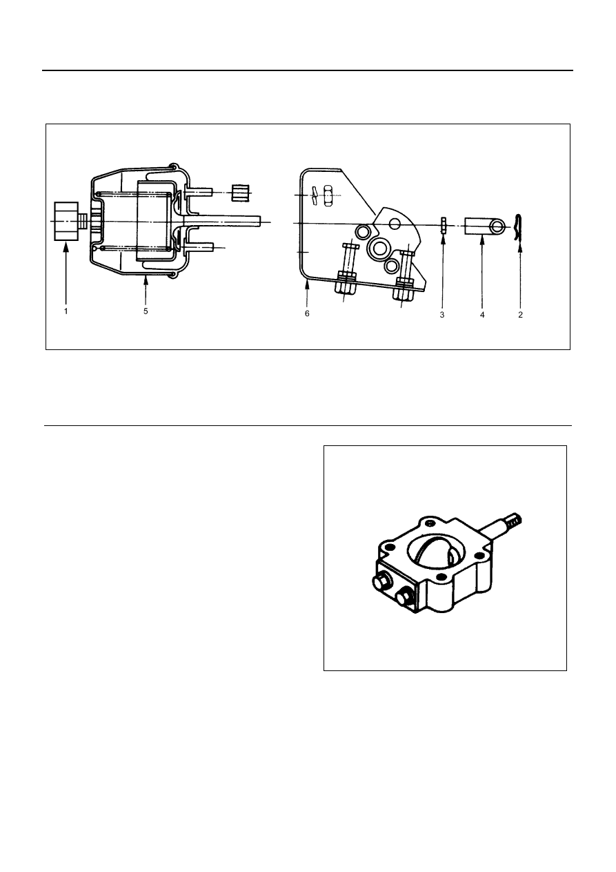
Exhaust Brake Unit
Disassembly
1. Exhaust Brake Valve Connector
2. Cotter Pin
3. Lock Nut
4. Clevis Joint
5. Power Chamber
6. Exhaust Valve Assembly
Inspection and Repair
Make the necessary adjustments, repairs, and part re-
placements if excessive wear or damage is discovered
during inspection.
Visual Inspection
Visually inspect the following parts for excessive wear
and damage.
If excessive wear or damage is discovered during in-
spection, the part(s) must be replaced.
• Exhaust brake valve
• Exhaust brake shaft
• Butterfly valve
• Bushings
• Power chamber
Power Chamber
(1) The exhaust brake valve should operate smoothly
when the negative pressure (400 mmHg to 700 mmHg)
is applied to the power chamber via the vacuum pump.
Legend
1. Exhaust brake valve connector
4. Clevis joint
2. Cotter pin
5. Power chamber
3. Lock nut
6. Exhaust valve assembly
N5A0466E
N5A0375E