Content .. 1126 1127 1128 1129 ..
Isuzu N-Series. Manual - part 1128
8-224 CAB AND CHASSIS ELECTRICAL
L-6
L-6
J-69
J-69
N-2
N-7
P-1
(12 V)
P-2
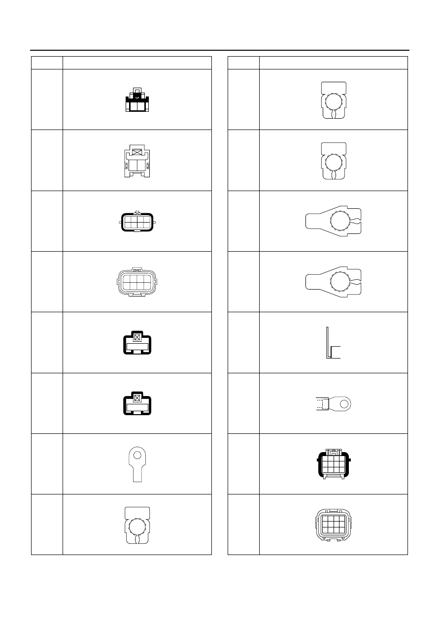
No.
Connector Face
002-022
1 2
002-023
2 1
008-007
1
2
3
4
5
6
7
8
008-008
1
2
3
4
5
6
7
8
001-009
1
001-009
1
000-003
000-004
P-1
(24 V)
P-4
P-2
(24 V)
P-3
P-5
(12 V)
P-5
(24 V)
J-69
J-69
No.
Connector Face
000-004
000-004
000-006
000-006
000-007
000-002
012-006
1 2 3 4
5 6 7 8
9 10 11 12
012-007
4 3 2 1
8 7 6 5
12 11 10 9