Isuzu N-Series. Manual - part 1125


  Index      Isuzu     Isuzu N-Series - service repair manual


Search            


Content   ..  1123  1124  1125  1126   ..


Isuzu N-Series. Manual - part 1125


8-212 CAB AND CHASSIS ELECTRICAL
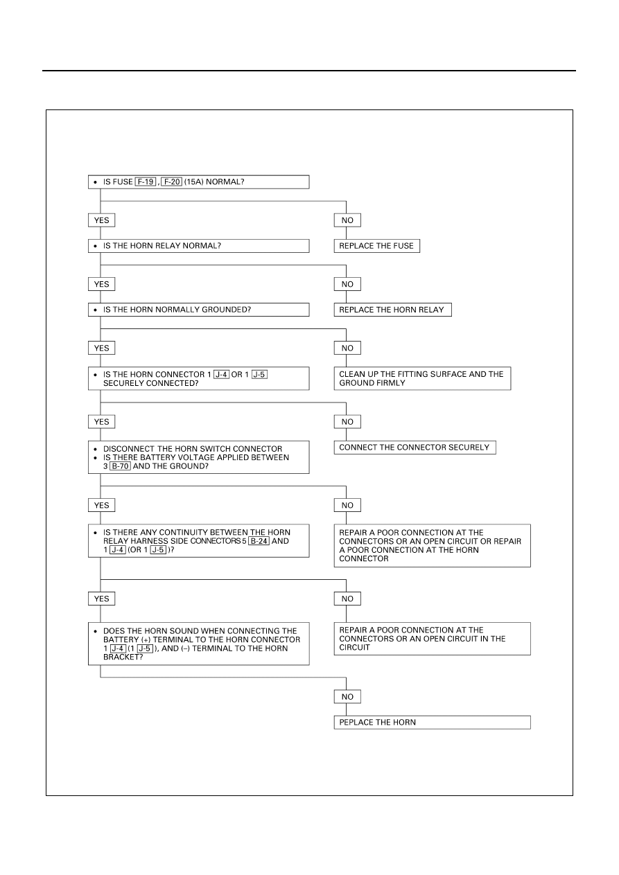
1. Horn
1-1. Horn Does Not Sound

N8A5222E

CAB AND CHASSIS ELECTRICAL 8-213

1-2. Horn Does Not Shut Off

2. Backup Light
2-1. Backup Lights Inoperative

N8A5224E

• IS FUSE  F-16  (10A) NORMAL?

• IS  J-9  SECURELY GROUNDED?

YES

NO

REPLACE THE FUSE

• TURN THE STARTER SW ON

• IS THE BATTERY VOLTAGE APPLIED BETWEEN THE

BACKUP LIGHT SWITCH HARNESS SIDE CONNECTOR
1  E-10  (OR 1  J-49  )AND THE GROUND?

YES

NO

GROUND IT SECURELY

• ENTER THE TRANSMISSION SHIFT LEVER TO

REVERSE POSITION 

• WHEN REMOVE THE CONNECTOR OF THE BACKUP

LIGHT SWITCH, IS THERE ANY CONTINUITY 
BETWEEN THE SW SIDE CONNECTORS 1  E-10  AND 
2  E-10  (OR 1  J-49  AND 2  J-49  )?

YES

NO

REPAIR A POOR CONNECTION AT THE
CONNECTORS OR AN OPEN CIRCUIT BETWEEN
FUSE  F-16  (10A) AND 1  E-10  OR 1  J-49  

REPAIR A POOR CONNECTION AT THE CONNECTORS 
OR AN OPEN CIRCUIT BETWEEN THE BACKUP LIGHT
SWITCH HARNESS SIDE CONNECTORS 2  E-10  
(OR 2  J-49  )AND 4  H-16

YES

NO

REPAIR OR REPLACE THE BACKUP LIGHT
SWITCH OR INHIBITOR SW

N8A0189E

8-214 CAB AND CHASSIS ELECTRICAL

2-2. Backup Light on the Left (or Right) Side Inoperative

2-3. Backup Light Remains on

Starter Switch

Refer to “START AND CHARGING” in this section.

Horn

Inspection
Check to see if horn sound when a battery voltage be-
tween horn terminal and the fixing bracket. Repair or re-
place the horn when the result of inspection is found
abnormal.

N8A5226E

REPAIR OR REPLACE THE BACKUP LIGHT SW OR INHIBITOR SW

N8A0191E

N8A0192E

CAB AND CHASSIS ELECTRICAL 8-215

Removal
Preparation:
Disconnect the battery ground cable.

1. Bumper

Refer to “BUMPER” in section 2.

2. Horn

Disconnect the connector (3).

Installation
To install, follow the removal steps in the reverse order.

Horn Switch

Inspection
With the contact point of the horn switch pressed to the
switch bracket, check the continuity between the con-
nector terminal and the bracket of the switch.
Check the contact condition between horn contact of the
combination switch and contact plate of steering wheel.
Repair or replace the switch when the result of inspec-
tion is found abnormal.

Removal
Preparation:
Disconnect the battery ground cable.

1. Horn Pad

1) Hold the horn pad and pull it upward.

2. Steering Wheel

1) Remove the steering shaft nut.
2) Remove the steering wheel by using steering

wheel remover.
(Refer to Section 3B4 “STEERING COLUMN”
for steering wheel removal steps.)

3. Horn Switch

Installation
To install, follow the removal steps in the reverse order,
noting the following point.

1. Tighten the steering shaft nut to the specified

torque.

Tighten:
Shaft nut to 49 N

⋅m (5 kg⋅m / 36 lb⋅ft)

1

2

3

N8A5485E

N8A0194E

N8A5231E


Content   ..  1123  1124  1125  1126   ..