Isuzu N-Series. Manual - part 1119


  Index      Isuzu     Isuzu N-Series - service repair manual


Search            


Content   ..  1117  1118  1119  1120   ..


Isuzu N-Series. Manual - part 1119


8-188 CAB AND CHASSIS ELECTRICAL

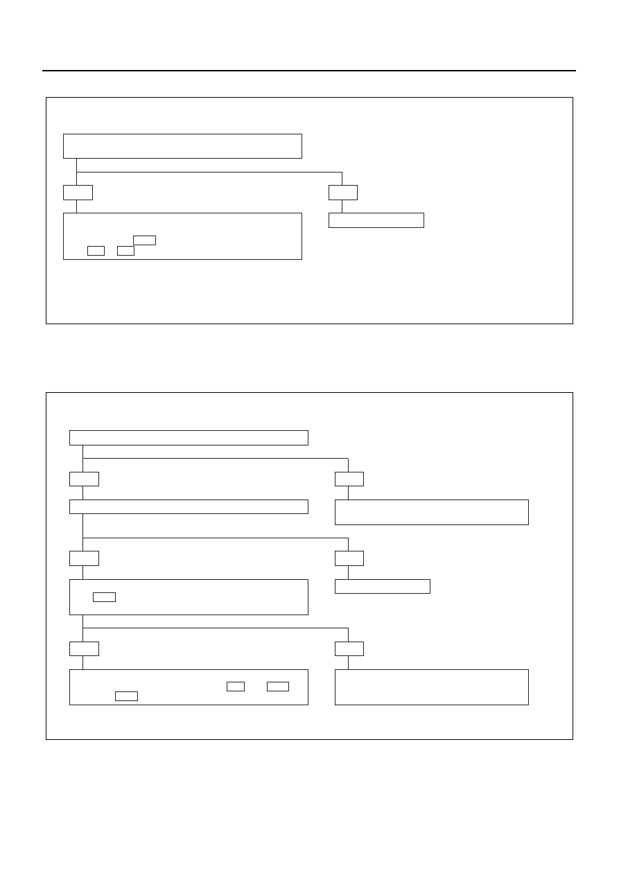
4. Taillight on the Left (or Right) Side Inoperative

Notice:
Figure in parenthesis “( )” indicates place of inspection for taillight on the right side.

5. License Plate Light Inoperative

• IS TAILLIGHT BULB ON THE LEFT (OR RIGHT) SIDE

NORMAL?

• REPAIR A POOR CONNECTION AT THE CONNECTORS

OR AN OPEN CIRCUIT BETWEEN CONNECTOR
TERMINAL 4  H-16  AND TAILLIGHT CONNECTOR 
1  R-1 ( 1  R-6 )

YES

NO

REPLACE THE BULB

N8A0163E

• ARE BOTH TAILLIGHTS OPERATIVE?

• IS THE LICENSE PLATE LIGHT BULB NORMAL?

YES

NO

TURN THE TAILLIGHTS ON (REFER TO
TAILLIGHT DIAGNOSIS IN THIS SECTION)

YES

NO

REPLACE THE BULB

  IS THERE BATTERY VOLTAGE APPLIED BETWEEN 

5  H-16  AND THE GROUND WHEN TURNING THE
LIGHTING SWITCH ON?

• REPAIR A POOR CONNECTION AT THE CONNECTORS

OR AN OPEN CIRCUIT BETWEEN 1  R-2 OR 1  R-14
AND 7  H-16 

YES

NO

REPAIR A POOR CONNECTION AT THE
CONNECTORS OR AN OPEN CIRCUIT IN THE
CIRCUIT

N8A0164E

CAB AND CHASSIS ELECTRICAL 8-189

6. Marker Light Inoperative

Lighting Switch

Refer to “HEADLIGHT, FOG LIGHT AND CORNERING
LIGHT” in this section.

Clearance Light/Bulb

Removal

1. Remove the battery ground cable at the battery.
2. Remove the front combination light.

• Open the cab door. Insert a screwdriver (1) into

the space between the cab and the cab door.
Use the screwdriver to force out the stud pin at
the center of the grommet (the pin securing the
front combination light).

• Remove the fixing screw.

N8A5191E

Door side

Cab side

1

N8A5471E

8-190 CAB AND CHASSIS ELECTRICAL

• Remove the two catches.
• Remove the front combination light (1) connec-

tor.

3. Remove the clearance light bulb.

• Turn the bulb socket (3) to the left to remove it.
• Press the bulb (2) in and turn it to the left to re-

move it from the socket.

Installation
Installation procedure of cornering/clearance light bulb

1. Install the cornering/clearance light bulb.

• While pressing the bulb (2), turn it clockwise to

fit.

Notice:
Do not let the glass portion dirty with sebum etc.

• Turn the bulb socket (3) clockwise to fit.

2. Installation procedure of front combination light as-

sembly

• Connect the connector of the combination light

assembly.

• Position it by aligning two pawls with the groove

of H/L.

• Fit the iron PIN (1) in the upper portion of the

side by aligning it with the center of correspond-
ing grommet.

Notice:
Push it into securely with a force of approx. 250 N (25
kgf) until click is heard.

• Pull the front combination light assembly lightly

toward the front of vehicle to make sure that the
PIN and grommet are engaged securely.

• Tighten one bolt in the lower portion of front

combination light assembly.

3. Hook the seal rubber on two projections under H/L.
4. Connect the battery ground cable.
5. Check lighting of each light.

Taillight Bulb

Removal

1. Lens
2. Bulb

Installation
To install, follow the removal steps in the reverse order.

1

3

2

N8A5477E

1

3

2

N8A0442E

N8A0167E

CAB AND CHASSIS ELECTRICAL 8-191

License Plate Light Bulb

Removal

1. Cover
2. Lens
3. Bulb

Installation
To install, follow the removal steps in the reverse order.

Turn Signal Light, Hazard Warning Light,
and Stoplight

General Description

The circuit consists of the starter switch, turn signal light
(front and rear), turn signal light switch, hazard warning
light, flasher unit, stoplight and stoplight switch.
When turning on the respective switches with the starter
switch on, the turn signal light will operate. When the
turn signal light is flashing, the indicator light in the meter
also starts flashing. When the hazard warning switch is
turned on, the current flows to the flasher unit through
the hazard warning switch to cause the hazard warning
light to flash, independent of the position of the starter
switch. At the same time, the indicator lights in the meter
also start flashing.
The stoplight switch will turn on and the light comes on
once the brake pedal is depressed, independent of the
position of the starter switch.

N8A0168E


Content   ..  1117  1118  1119  1120   ..