Isuzu N-Series. Manual - part 1034


  Index      Isuzu     Isuzu N-Series - service repair manual


Search            


Content   ..  1032  1033  1034  1035   ..


Isuzu N-Series. Manual - part 1034


CAB AND CHASSIS ELECTRICAL 8-241

Starter Switch

Refer to “START AND CHARGING” in this section.

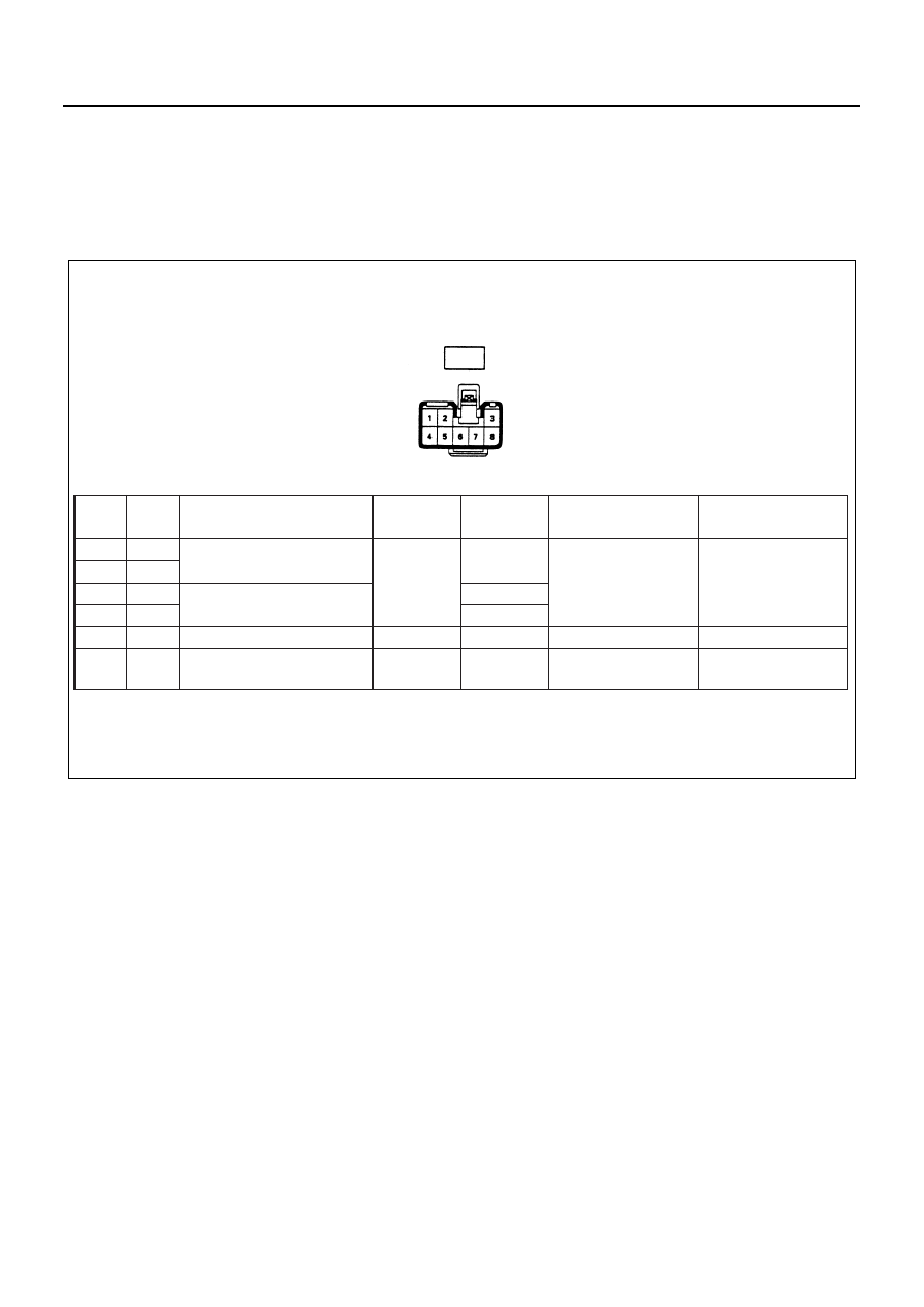
Power Window Switch-driver Side

Circuit Inspection
Disconnect the switch connectors to check the voltage and the continuity between the harness side connector termi-
nals.

Termi-

Item

Connect-

Wire

nal

Connected to

to be

ing

Checking conditions

Standard

color

No.

checked

terminal

1

L/W

2

L

Driver seat side motor

1-2

4

G/Y

4-5

-

Continuity

5

R/Y

5-4

6

L/B

Power window relay

Voltage

6-Ground

Starter SW "ON"

Battery voltage

8

B

Ground

Continuity

8-Ground

-

Continuity

(resistance)

Continuity

(resistance)

Passenger side power
window SW

Harness side

D-3

N8A0234E

8-242 CAB AND CHASSIS ELECTRICAL

Inspection
Check the continuity between the connector terminals of the switch.
Repair or replace the switch when the result of inspection is found abnormal.

Removal
Preparation:
Disconnect the battery ground cable.

1. Switch

1) Insert the screw driver to the cut off portion to

remove the switch.

2) Disconnect the connector.

Driver side

Passenger side

6

1

2

8

6

5

4

8

UP

OFF

DOWN

UP

OFF

DOWN

LOCK

Window

Terminal

No.

SW

position

D-3

Switch side

N8A0235E

N8A0236E

CAB AND CHASSIS ELECTRICAL 8-243

Installation
To install, follow the removal steps in the reverse order.

Power Window Switch-passenger Side

Circuit Inspection
Disconnect the switch connectors to check the voltage and the continuity between the harness side connector termi-
nals.

Inspection
Check the continuity between the connector terminals of
the switch.
Repair or replace the switch when the result of inspec-
tion is found abnormal.

N8A5280E

8-244 CAB AND CHASSIS ELECTRICAL

Removal
Preparation:
Disconnect the battery ground cable.

1. Switch

1) Insert the screw driver to the cut off portion to

remove the switch.

2) Disconnect the connector.

Installation
To install, follow the removal steps in the reverse order.

Driver Seat Side Power Window Motor

Inspection
Before checking to see if the motor functions correctly,
be sure to check the circuit through the connector 
of the driver’s power window switch.
If the motor does not operate smoothly, either the motor
or the circuit between the switch and the motor is defec-
tive.

1. Circuit inspection of the driver side window switch

Disconnect the switch connector and apply battery
voltage to the harness side connector terminals to
check its function.

1

2

4

3

5

UP

OFF

DOWN

Terminal

No.

SW position

 Switch side

D-7

N8A0238E

N8A0239E

D-3


Content   ..  1032  1033  1034  1035   ..