Isuzu N-Series. Manual - part 1012


  Index      Isuzu     Isuzu N-Series - service repair manual


Search            


Content   ..  1010  1011  1012  1013   ..


Isuzu N-Series. Manual - part 1012


CAB AND CHASSIS ELECTRICAL 8-153

Caution:
Do not touch the glass portion of the new bulb with your
fingers.

Headlight Replacement

Removal
Preparation: Disconnect the battery ground cable.

1. Remove the battery ground cable at the battery.
2. Remove the seal rubber (3).

• Remove the seal rubber from beneath the

headlight.

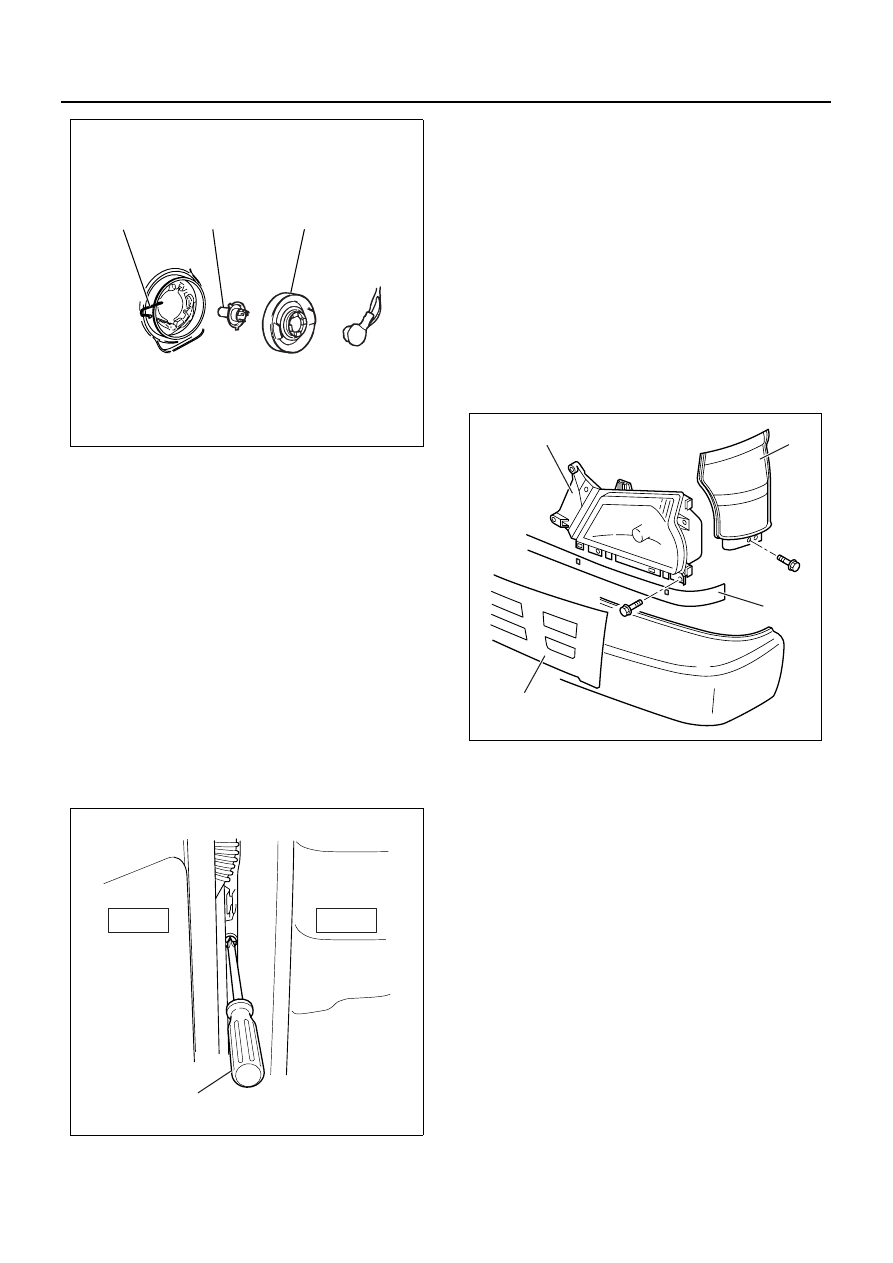
3. Remove the front combination light (2).

• Open the cab door. Insert a screwdriver (1) into

the space between the cab and the cab door.
Use the screwdriver to force out the stud pin at
the center of the grommet (the pin securing the
front combination light).

• Remove the fixing screw.
• Remove the two catches.

• Remove the front combination light connector.

4. Remove the front grille (4).

• Remove the bolt at the center of the front grille.
• Remove the four clips securing the front grille.
• The grille is secured by 4 clips (2 clips at the in-

side of each headlight). Pull the grille toward
you to remove it.

5. Remove the front corner panel.
6. Remove the headlight (1).

• Remove the four bolts securing the headlight

(loosen the fixing bolts at the bottom of the front
side panel to create working space).

• Remove the headlight clips.
• Remove the headlight connector.

Installation

1. Assemble the headlight assembly (1).

• Connect the connector.
• Fix it to body panel with four bolts (5).

2. Assemble the front panel side.

(Refer to “DOOR” in section 2.)

3. Install the front grille (4).
4. Install the front combination assembly (2).

1) Position it by aligning two pawls with the groove

of H/L.

2) Fit the iron PIN in the upper portion by aligning

it with the center of corresponding grommet.

Notice:
Push it into securely with a force of approx. 250 N (25
kgf) until click is heard.

3) Pull the front combination light assembly lightly

toward the front of vehicle to make sure that the
PIN and grommet are engaged securely.

4) Tighten one bolt (6) in the lower portion of front

combination light assembly.

5) Hook the seal rubber (3) on two projections un-

der H/L.

1

2

3

N8A5468E

Door side

Cab side

1

N8A5471E

1

2

3

4

N8A5472E

8-154 CAB AND CHASSIS ELECTRICAL

5. Connect the battery ground cable.
6. Check the operation and lighting of each lamp.

Aiming of Headlight

Preparation: Place the unloaded vehicle on a level sur-
face and check to see if the inflation pressure of the tires
is correct, the lenses are clean, and the battery is suffi-
ciently charged. Adjust the aim with the headlight tester.
When adjusting, follow the procedure of the tester man-
ufacturer’s.

Vertical Adjustment

Insert the tip of a screwdriver into the hole beneath the
headlight (the shaft of the screwdriver must be slanted
up) until contact is made with the head of the adjusting
screw. Turn the screw to adjust headlight focus up or
down.
Two vertical aim screws should be turned in the same
direction at the same time to adjust aiming.

Horizontal Adjustment

Insert the tip of a screwdriver into the hole beneath the
headlight (the shaft of the screwdriver must be slanted
up) until contact is made with the head of the adjusting
screw. Turn the screw to adjust headlight focus to the
left or right.

Cornering Light Bulb Replacement

Removal

1. Remove the battery ground cable at the battery.
2. Remove the front combination light.

• Open the cab door. Insert a screwdriver (1) into

the space between the cab and the cab door.
Use the screwdriver to force out the stud pin at
the center of the grommet (the pin securing the
front combination light).

1

2

3

4

6

5

N8A0441E

N8A5473E

N8A5474E

N8A5475E

CAB AND CHASSIS ELECTRICAL 8-155

• Remove the fixing screw.
• Remove the two catches.
• Remove the front combination light (1) connec-

tor.

3. Remove the cornering light bulb.

• Turn the cornering / clearance bulb socket (3)

to the left to remove it.

• Press the bulb (2) in and turn it to the left to re-

move it from the socket.

Installation

1. Install the cornering / clearance bulb.

• While pressing the bulb (2), turn it clockwise to

fit.

Notice:
Do not let the glass portion dirty with sebum etc.

• Turn the bulb socket (3) clockwise to fit.

2. Installation procedure of front combination light as-

sembly

• Connect the connector of the front combination

light assembly.

• Position it by aligning two pawls with the groove

of H/L.

• Fit the iron PIN (1) in the upper portion of the

side by aligning it with the center of correspond-
ing grommet.

Notice:
Push it into securely with a force of approx. 250 N (25
kgf) until click is heard.

• Pull the front combination light assembly lightly

toward the front of vehicle to make sure that the
PIN and grommet are engaged securely.

• Tighten one bolt in the lower portion of front

combination light assembly.

3. Hook the seal rubber on two projections under H/L.
4. Connect the battery ground cable.
5. Check lighting of each light.

Door side

Cab side

1

N8A5471E

1

3

2

N8A5477E

1

3

2

N8A0442E

8-156 CAB AND CHASSIS ELECTRICAL

Fog Light Bulb

Removal

1. Remove the battery ground cable at the battery.
2. Remove the four screws (1) to remove the cover

which holds fog light assembly (2).

3. Remove the connector (3).
4. Remove the fog light assembly (2).

5. Bulb

• Push the clip (1) inward as arrow to remove.
• Remove the bulb (2).

Installation

1. Install the fog light bulb.

• Set the fog light bulb (2).
• Hook the clip (1) to secure fog light bulb.

2. Connect the two locations of connector (4).
3. Install the fog light assembly.

• Hold the fog light (2) with right and left covers

(1) and secure it with four screws (3).

Notice:
Make sure that “TOP” mark on the lens comes upside.

4. Connect the battery ground cable.
5. Check lighting.

2

1

3

N8A5478E

1

2

N8A5479E

1

2

N8A0443E

2

1

4

3

N8A0444E


Content   ..  1010  1011  1012  1013   ..