Isuzu N-Series. Manual - part 61


  Index      Isuzu     Isuzu N-Series - service repair manual


Search            


Content   ..  59  60  61  62   ..


Isuzu N-Series. Manual - part 61


1B-14 AIR CONDITIONING

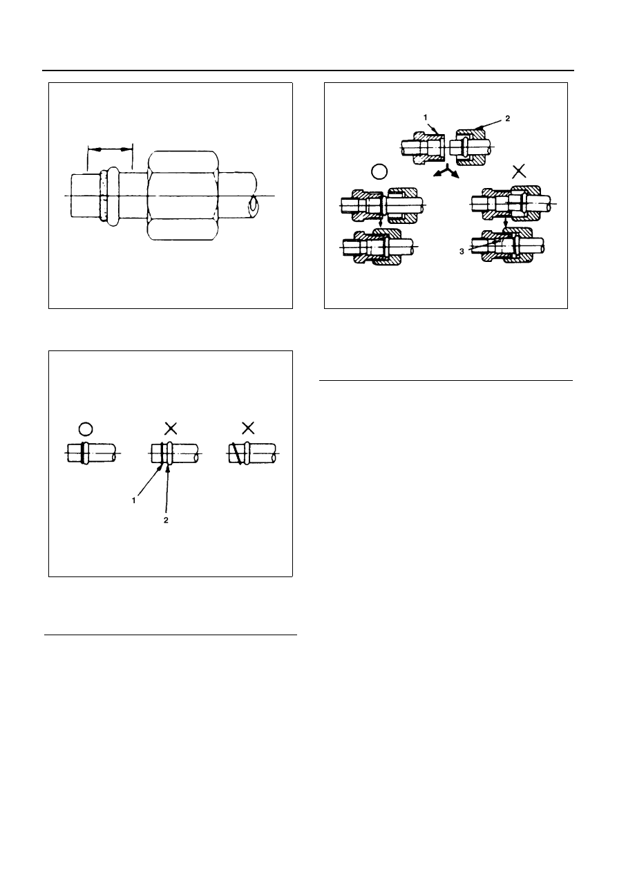
O-rings must be closely aligned with raised portion of re-
frigerant line.

Insert nut into union. First tighten nut by hand as much
as possible. Then, tighten nut to specified torque.
(Refer to “SERVICE INFORMATION” for Fixing Torque
in section 00)

Leak at Refrigerant Line Connections

1. Check the torque on the refrigerant line fitting and,

if too loose, tighten to the specified torque.

• Use two wrenches to prevent twisting and damage

to the Line.

• Do not over tighten.

2. Perform a leak test on the refrigerant line fitting.
3. If the leak is still present, discharge and recover the

refrigerant from the system.

4. Replace the O-rings.

• O-rings cannot be reused. Always replace with

new ones.

• Be sure to apply specified compressor oil to the

new O-rings.

5. Retighten the refrigerant line fitting to the specified

torque.

• Use two wrenches to prevent twisting and damage

to the line.

6. Evacuate, charge and retest the system.

Leak in The Hose

If the compressor inlet or outlet hose is leaking, the en-
tire hose must be replaced. Refrigerant hose must not
be cut or spliced for repair.

1. Locate the leak.
2. Discharge and recover the refrigerant.
3. Remove the hose assembly.

• Cap the open connections at once.

4. Connect the new hose assembly.

• Use two wrenches to prevent twisting or damage to

the hose fitting.

Legend

1. O-ring
2. Raised portion

N1A0064E

N1A0065E

Legend

1. Union
2. Nut
3. Damage

N1A0066E

AIR CONDITIONING 1B-15

• Tighten the hose fitting to the specified torque.

5. Evacuate, charge and test the system.

Compression Leaks

If leaks are located around the compressor shaft seal or
shell, replace or repair the compressor.

Recovery, Recycling, Evacuation and Charging

Handling Refrigerant-134a
Air conditioning systems contain R-134a.
This is a chemical mixture which requires special han-
dling procedures to avoid personal injury.

• Always wear safety goggles and protective gloves.
• Always work in a well-ventilated area. Do not weld

or steam clean on or near any vehicle-installed air
conditioning lines or components.

• If R-134a should come in contact with any part of

the body, flush the exposed area with cold water
and immediately seek medical help.

• If it is necessary to transport or carry any container

of R-134a in a vehicle, do not carry it in the passen-
ger compartment.

• If it is necessary to fill a small R-134a container

from a large one, never fill the container complete-
ly. Space should always be allowed above the liq-
uid for expansion.

• R-134a and R-12 should never be mixed as their

compositions are not the same.

• R-134a PAG oil tends to absorb moisture more

quickly than R-12 mineral oil and, therefore, should
be handled more carefully.

• Keep R-134a containers stored below 40

°C

(100

°F).

Warning:

WARNING:

• SHOULD R-134a CONTACT YOUR EYE(S),

CONSULT A DOCTOR IMMEDIATELY.

• DO NOT RUB THE AFFECTED EYE(S). IN-

STEAD, SPLASH QUANTITIES OF FRESH
COLD WATER OVER THE AFFECTED AREA TO
GRADUALLY RAISE THE TEMPERATURE OF
THE REFRIGERANT ABOVE THE FREEZING
POINT.

• OBTAIN PROPER MEDICAL TREATMENT AS

SOON AS POSSIBLE. SHOULD THE R-134a
TOUCH THE SKIN, THE INJURY MUST BE
TREATED THE SAME AS SKIN WHICH HAS
BEEN FROSTBITTEN OR FROZEN.

Refrigerant Recovery

The refrigerant must be discharged and recovered by
using ACR

4

 (R-134a Refrigerant Recovery/ Recycling/

Recharging/ System) (1) or equivalent before removing
or mounting air conditioning parts.
ACR

4

 (115V 60Hz): 5-8840-0629-0 (J-39500-A)

ACR

4

 (220-240V 50/60Hz): 5-8840-0630-0 (J-39500-

220A)

ACR

4

 (220-240V 50/60Hz Australian model): 5-88410-

0631-0 (J-39500-220ANZ)

1. Connect the high and low charging hoses of the

ACR

4

 (or equivalent) as shown.

2. Recover the refrigerant by following the ACR

4

Manufacture’s Instructions.

3. When a part is removed, put a cap or a plug on the

connecting portion so that dust, dirt or moisture
cannot get into it.

Refrigerant Recycling

Recycle the refrigerant recovered by ACR

4

 or equiva-

lent.
For the details of the actual operation, follow the steps
in the ACR

4

 Manufacture’s Instructions.

ACR

4

 (115V 60Hz): 5-8840-0629-0 (J-39500-A)

ACR

4

 (220-240V 50/60Hz): 5-8840-0630-0 (J-39500-

220A)
ACR

4

 (220-240V 50/60Hz Australian model): 5-8840-

0631-0 (J-39500-220ANZ)

Evacuation of The Refrigerant System

Notice:

Explained below is a method using a vacuum pump. Re-
fer to ACR

4

 (or equivalent) manufacture’s instructions

when evacuating the system with ACR

4

 (or equivalent).

Air and moisture in the refrigerant will cause problems in
the air conditioning system.
Therefore, before charging the refrigerant, be sure to
evacuate air and moisture thoroughly from the system.

N1A0067E

1B-16 AIR CONDITIONING

1. Connect the gauge manifold.

• High-pressure valve (HI) — Discharge-side
• Low-pressure valve (LOW) — Suction-side

2. Discharge and recover the refrigerant.
3. Connect the center hose of the gauge manifold set

to the vacuum pump inlet.

4. Operate the vacuum pump, open shutoff valve and

then open both hand valves.

5. When the low-pressure gauge indicates approx.

750 mmHg (30 inHg), continue the evacuation for
5 minutes or more.

6. Close both hand valves and stop the vacuum

pump.

7. Check to ensure that the pressure does not change

after 10 minutes or more.

• If the pressure changes, check the system for

leaks.

• If leaks occur, retighten the refrigerant line connec-

tions and repeat the evacuation steps.

8. If no leaks are found, again operate the vacuum

pump for 20 minutes or more. After confirming that
the gauge manifold pressure is at 750 mmHg(30
inHg), close both hand valves.

9. Close positive shutoff valve.

Stop the vacuum pump and disconnect the center
hose from the vacuum pump.

Charging The Refrigerant System

There are various methods of charging refrigerant into
the air conditioning system.
These include using ACR

4

 (R-134a Refrigerant Recov-

ery/ Recycling/ Recharging/ System) or equivalent and
direct charging with a manifold gauge charging station.
ACR

4

 (115V 60Hz): 5-8840-0629-0 (J-39500-A)

ACR

4

 (220-240V 50/60Hz): 5-8840-0630-0 (J-39500-

220A)
ACR

4

 (220-240V 50/60Hz Australian model): 5-8840-

0631-0 (J-39500-220ANZ)
Charging procedure

• ACR

4

 (or equivalent) method

For the charging of refrigerant recovery by ACR

4

(1), follow the manufacture’s instruction.

N1A0068E

N1A0067E

AIR CONDITIONING 1B-17

• Direct charging with a manifold gauge charging

station method
Handling the charging valve handle when installing
refrigerant container.

1. Before attaching the charge valve to the refrigerant

container, turn the charge valve handle (1) coun-
terclockwise until the needle (2) is fully retracted.

2. Turn the plate nut (3) counterclockwise until it

reaches its highest position relative to the charge
valve.

3. Install the charge valve onto the refrigerant con-

tainer (4).

4. Turn the plate nut clockwise and connect the cen-

ter hose of the manifold gauge to the charge valve
(5).

5. Tighten the plate nut sufficiently by hand. Then turn

the charge valve handle clockwise to lower the
needle and bore a hole in the refrigerant container.

6. Turn the charge valve handle counterclockwise to

raise the needle. The refrigerant in the refrigerant
container is charged into the air conditioning sys-
tem by the operation of the manifold gauge.

• Be absolutely sure not to reuse the emptied refrig-

erant container.

Legend

1. Charge valve handle

3. Vacuum pump

2. Service container

N1A0070E


Content   ..  59  60  61  62   ..