Isuzu engine 4j series. Manual - part 55


  Index      Isuzu     Isuzu engine 4j series - service manual


Search            


Content   ..  53  54  55  56   ..


Isuzu engine 4j series. Manual - part 55


6A1 – 88  4JB1/4JB1T/4JB1TC/4JG2 - ENGINE

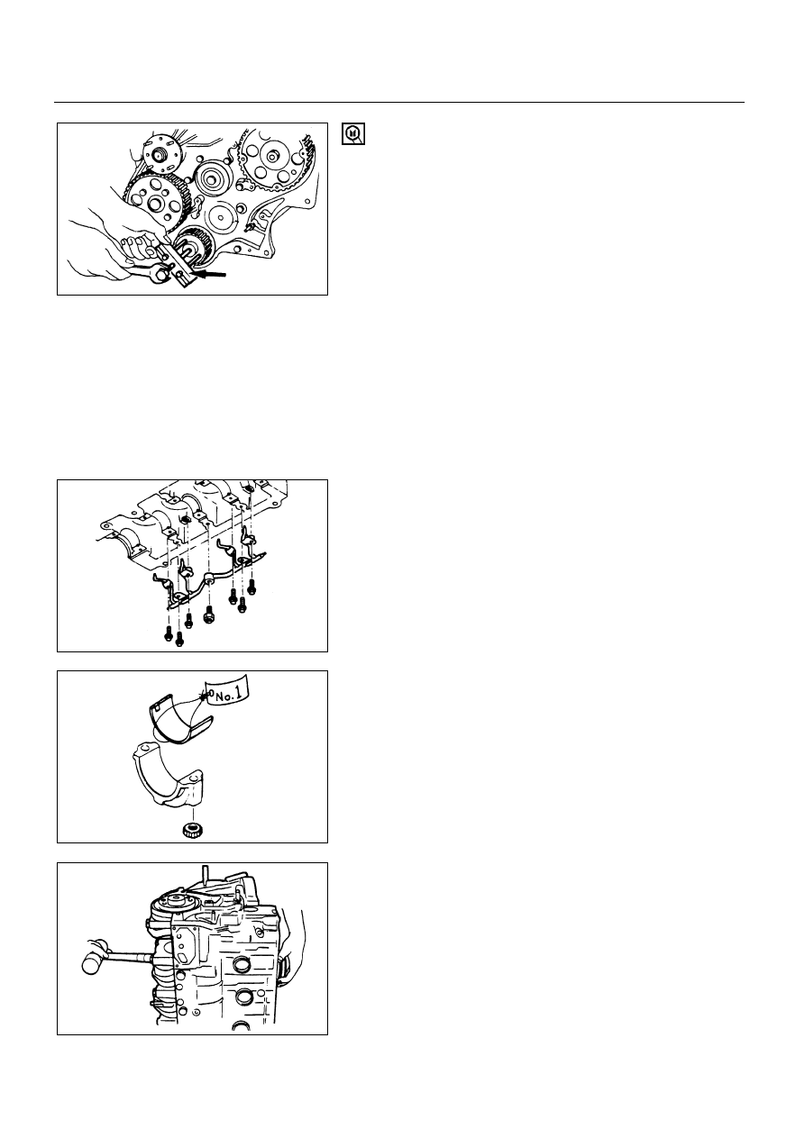
9) Crankshaft timing pulley

Block the crankshaft with a piece of hard wood.

Use the crankshaft timing pulley puller to remove the
timing pulley.
Crankshaft Timing Pulley Puller: 5-8840-2035-0

10) Injection pump timing pulley
11) Injection pump

Above works refer to “CYLINDER BLOCK
ASSEMBLY” Section in this manual.

12) Camshaft timing pulley

5. Oil Pan Assembly

6. Oil Pump Assembly

Above works refer to “CAMSHAFT AND TAPPET” Section
in this manual.

7. Piston Cooling Oil Pipe

Remove the oil pipe from cylinder block.

8. Piston and Connecting Rod Assembly

If the connecting rod lower bearings are to be
reinstalled, mark their fitting positions by tagging each
bearing with the cylinder number from which it was
removed.

Remove carbon deposits from the upper portion of the
cylinder wall with a scraper before removing the piston
and connecting rod.
Move the piston to the top of the cylinder and tap it
with a hammer grip or similar object from the
connecting rod lower side to drive it out.

6A1-88-1.tif

6A1-88-2.tif

6A1-88-3.tif

6A1-88-4.tif

4JB1/4JB1T/4JB1TC/4JG2 – ENGINE  6A1 – 89

If the connecting rod upper bearings are to be
reinstalled, mark their fitting positions by tagging each
bearing with the cylinder number from which it was
removed.

9. Front Oil Seal (Belt Drive Model)

With the oil seal pushed in deep, install the special tool
as shown in the illustration to remove the oil seal.
Front Oil Seal Remover: 5-8840-2362-0

10. Timing Gear Housing

10a. Timing Pulley Housing

11. Water Pump Assembly

12. Flywheel and Cylinder Body Rear Plate

Set the flywheel stopper.

Loosen the flywheel fixing bolts then remove the
flywheel.

Remove the cylinder block rear plate.

13. Rear Oil Seal (Gear and Belt Drive Model)

With the oil seal pushed in deep, install the special tool
as shown in the illustration to remove the oil seal.

Rear Oil Seal Remover: 5-8840-2360-0

NOTE:

Take care not to damage sealing surface of front plate
and crankshaft when removing oil seal.

14. Crankshaft and Main Bearing

1) Remove the main bearing caps and thrust washer.
2) Remover the crankshaft with care.
3) Remove the crankshaft upper bearing.

6A1-89-1.tif

6A1-89-2.tif

6A1-89-3.tif

6A1-89-4.tif

6A1 – 90  4JB1/4JB1T/4JB1TC/4JG2 - ENGINE

INSTALLATION

14. Crankshaft and Main Bearings

The crankshaft upper bearings have an oil hole and an
oil groove.  The lower bearings do not…

Install main bearings in the cylinder body and main
bearing cap respectively.

Apply new engine oil to upper and lower main
bearings.

Make sure that main bearing are in correct position.

Carefully wipe any foreign material from the upper
bearing.

Install the main bearings to the cylinder body and the
main bearing caps.

NOTE:

Do not apply engine oil to the bearing back faces and
the cylinder body bearing fitting surfaces.

Be sure that they are positioned correctly.

Apply new engine oil to the upper and lower main
bearing faces.

Carefully mount the crankshaft.

Apply engine oil to the thrust washer.

Install thrust washer on No.3 journal.
Oil grooves in thrust washer must face the crankshaft.

Apply the recommended liquid gasket or its equivalent
to the No.5 crankshaft bearing cap cylinder body fitting
surfaces at points and shown in the illustration.

NOTE:

Be sure that the bearing cap fitting surface is
completely free of oil before applying the liquid
gasket.

Do not allow the liquid gasket to obstruct the cylinder
thread holes and bearings.

6A1-90-1.tif

6A1-90-2.tif

6A1-90-3.tif

6A1-90-4.tif

4JB1/4JB1T/4JB1TC/4JG2 – ENGINE  6A1 – 91

Install the bearing caps with the bearing cap head
arrow mark facing the front of the engine.

Apply engine oil to the front of the engine.

Tighten the crankshaft bearing cap bolts to the
specified torque a little at a time in the sequence
shown in the illustration.

N∙m (kg∙m/lb∙ft)


167 (17.0/123)


NOTE:

Check to see that the crankshaft turns smoothly by
rotating it manually.

13. Crankshaft Rear Oil Seal

Use the oil seal installer to install the oil seal to the cylinder
body.
Rear Oil Seal Installer: 5-8840-2361-0

NOTE:

Wipe off rust and scraps clean from the press-in
portion of the oil seal.

Take note of the press-in direction of the oil seal.
1) Install the adapter of the special tool to the rear end of

the crankshaft with two bolts.

2) Install the oil seal to the outer circumference of the

adapter.

3) Insert the slave into the adapter portion, and tighten it

in with the bolt (M12x1.75L=70) until the adapter
section hits the slave.

4) Remove the adapter and the slave.
5) After installing the oil seal, check the measurement of

the oil seal.

Standard

mm (in)


12.2 - 12.8 (0.48 - 0.50)


12. Flywheel and Cylinder Body Rear Plate

Align the rear plate with the cylinder body knock pins.

Tighten the rear plate to the specified torque.

Rear Plate Bolts Torque

N∙m (kg∙m/lb∙ft)


82 (8.4/61)


6A1-91-1.tif

6A1-91-2.tif

6A1-92-3.tif


Content   ..  53  54  55  56   ..