Isuzu Trooper (2000 year). Manual - part 494


  Index      Isuzu     Isuzu Trooper - service repair manual 2000 year


Search            


Content   ..  492  493  494  495   ..


Isuzu Trooper (2000 year). Manual - part 494


8G–16 SEATS

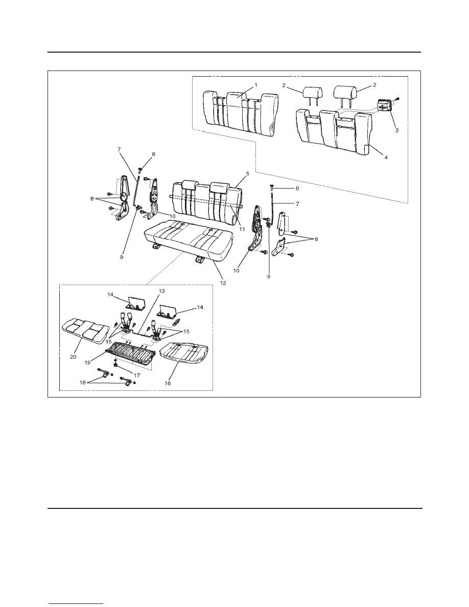
Disassembled View (Bench Type)

755RW021

Legend

(1) Trim Cover
(2) Pillow Assembly
(3) Band Hook Cover
(4) Pad & Frame Assembly
(5) Seat Back Assembly
(6) Release Knob
(7) Release Rod
(8) Device Cover
(9) Linkage Bush

(10) Reclining Device

(11) Connecting Shaft

(12) Seat Cushion Assembly
(13) Connecting Link
(14) Seat Lock Cover
(15) Rear Seat Belt Buckle and Lock Assembly
(16) Trim Cover
(17) Stopper Rubber
(18) Mounting Bracket
(19) Frame Assembly
(20) Pad Assembly

SEATS 8G–17

Disassembly (Bench Type)

1. Remove the device cover.
2. Remove the release knob.

D

Turn the knob to the counterclockwise to remove it.

3. Remove the release rod.

D

Disconnect the rod from the linkage bush.

4. Remove the reclining device.

755RS004

5. Remove the connecting shaft.
6. Remove the seat back assembly.
7. Remove the band hook cover.
8. Remove the pillow assembly.

D

Refer to the Disassembly (Split Type) in this
section.

755RS017

9. Remove the trim cover.

D

Open the fastener(3), and with close attention paid
to the hog rings and wire which connect the trim
cover and the pad and frame assembly, remove the
trim cover as you turn it up.

750RW011

10. Remove the pad & frame assembly.

11. Remove the seat cushion assembly.

12. Remove the seat lock cover.
13. Remove the rear seat belt buckle and lock assembly.
14. Remove the mounting bracket.
15. Remove the trim cover.

D

Remove the hog rings and pull the trim cover out
from the frame assembly groove.

D

With close attention paid to the hog rings and the
wire which connect the trim cover and the pad and
frame assembly, remove the trim cover while
turning it up.

16. Remove the frame assembly.
17. Remove the pad assembly.
18. Remove the stopper rubber.

8G–18 SEATS

Reassembly (Bench Type)

To reassemble,  follow the disassembly steps in the
reverse order, noting the following points.

1. Tighten the reclining device fixing bolts to the

specified torque.

Torque: 27 N·m (20 lb ft)

2. Loosen the rubber stopper lock nut(1) and adjust the

stopper rubber(3) so there is no clearance between
the bottom of the stopper and the carpet(2), while
ensuring the rear seat is firmly locked.
Tighten the lock nut securely.

755RS005

Rear Seat Foot Rest

Rear Seat Foot Rest and Associated Parts

676RY001

Legend

(1) Fixing Nut
(2) Front Seat

(3) Rear Seat Foot Rest
(4) Foot Rest Pad

SEATS 8G–19

Removal

1. Remove the foot rest pad.

676RS002

2. Remove the fixing nut.
3. Remove the rear seat foot rest.

Installation

To install, follow the removal steps in the reverse order.

Main Data and Specifications

Torque Specifications

E10RW007


Content   ..  492  493  494  495   ..