Index Isuzu Isuzu Trooper - service repair manual 2000 year
Search
Content .. 471 472 473 474 ..
Isuzu Trooper (2000 year). Manual - part 473
8F–39
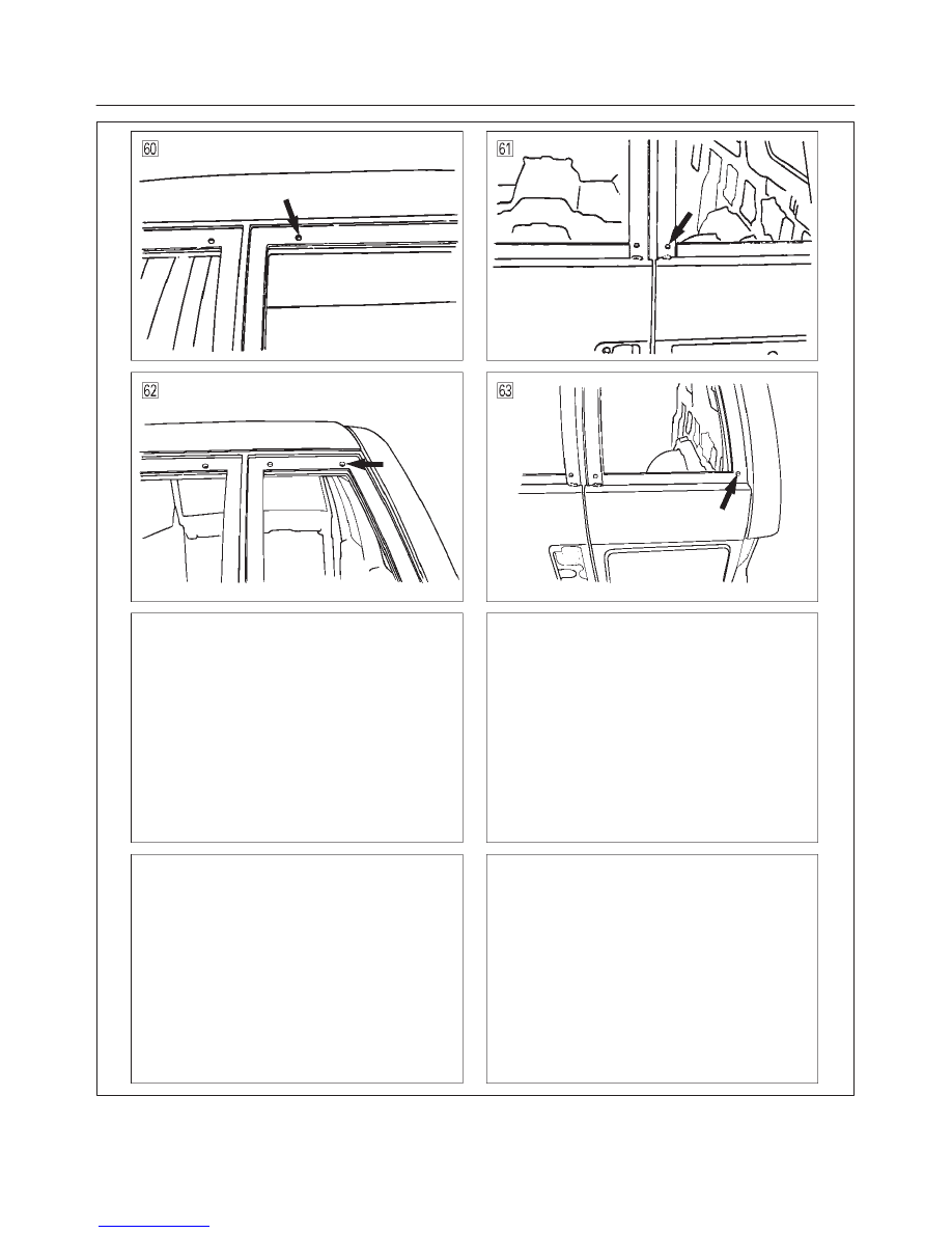
BODY STRUCTURE
A10RW013